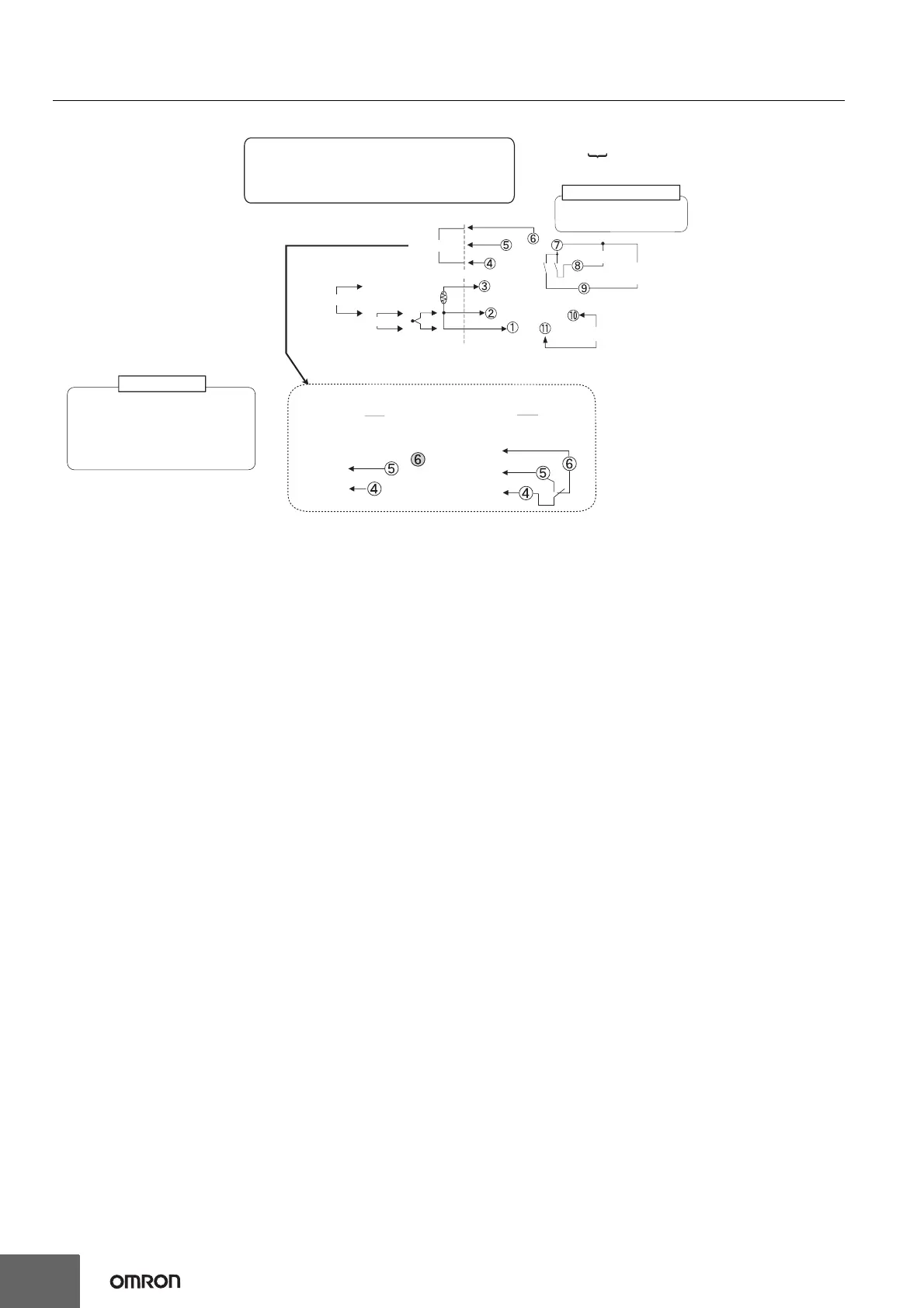
E5CC-800/E5CC-B-800/E5CC-U-800
12
E5CC-U-800
Note: 1. The application of the terminals depends on the model.
2. Do not wire the terminals that are shown with a gray background.
3. When complying with EMC standards, the cable that connects the sensor must be 30 m or less.
If the cable length exceeds 30 m, compliance with EMC standards will not be possible.
4. Connect M3.5 crimped terminals for the E5CC-U-800.
A
B
B
+
−
250 VAC, 3 A (resistive load)
Control output 1
•
•
Auxiliary output 1
Relay output
−
+
V
−
mA
+
The E5CC-U is set for a K-type thermocouple (input type =
5) by default. An input error (s.err) will occur if the input
type setting does not agree with the temperature sensor.
Check the input type.
Sensor (temperature/analog) input
Auxiliary output 2:
Control output (cooling side)
Control output 1:
Control output 1
100 to 240 VAC
24 VAC/DC (no polarity)
RW
Models with 1
Relya Output
QX
+
−
Models with 1
Voltage Output
(for Driving SSR)
Output 1
Q
Output 1
R
E5CC-UM-800
Control output 1
Auxiliary outputs 1 and 2
Voltage output (for driving SSR)
12 VDC, 21 mA
Relay output (three terminals used)
SPDT, 250 VAC, 3 A
(resistive load)
Input power supply
I
V
TC
Pt

 Loading...