EasyManuals Logo

Omron E5CC Communications Manual

Omron E5CC
224 pages
To Next Page IconTo Next Page
To Previous Page IconTo Previous Page
Page #197 background imageLoading...
Page #197 background image
6 - 83
6 Programless Communications
E5@C Digital Temperature Controllers Communications Manual (H175)
6-10 Connecting to MELSEC iQ-R-series PLCs
6
6-10-5 Checking Operation
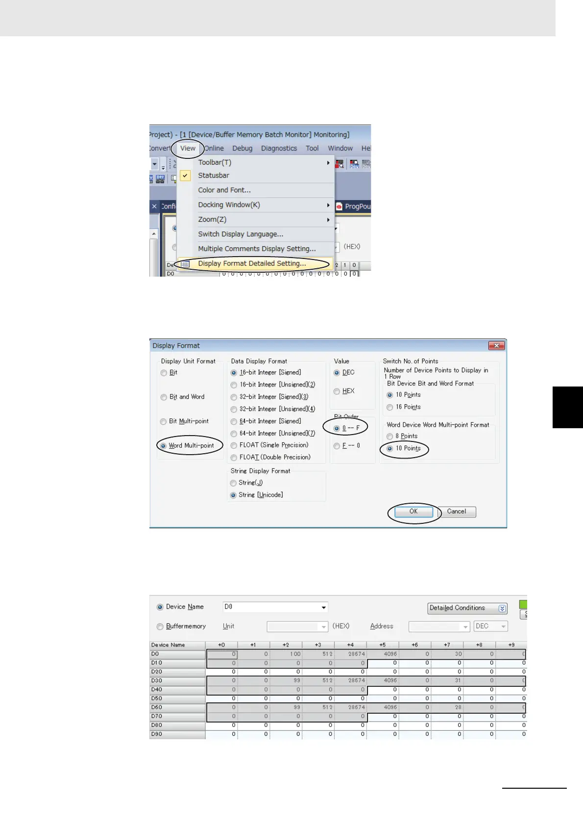
(3) To make the value easier to check, change the values that are displayed to decimal
values.
Select View Display format Detailed Setting.
Set the display format settings shown in the following dialog box.
Set the Display Unit Format to Word Multi-point, set the Bit Order to 0-F, set the Word
Device Word Multi-point Format to 10 Points, and then click the OK Button.
The display will appear as shown below after the display format is changed.
The area where monitor values are checked is called the upload area.
D0 to D14 is the upload area for the No. 0 Controller (E5CC), D30 to D44 is the upload area
for the No. 1 Controller, and D60 to D74 is the upload area for the No. 2 Controller.
No.0
No.1
No.2

Table of Contents

Other manuals for Omron E5CC

Questions and Answers:

Question and Answer IconNeed help?

Do you have a question about the Omron E5CC and is the answer not in the manual?

Omron E5CC Specifications

General IconGeneral
Number of Display Digits4 digits
Number of Control Outputs1
Control MethodON/OFF
Input TypeThermocouple, RTD, Analog voltage, Analog current
Supply Voltage100 to 240 VAC
Output TypeRelay, Voltage, Current
Display TypeLCD
Size48 x 48 mm
Mounting MethodPanel mount
Control OutputRelay, Voltage, Current
Alarm OutputRelay
CommunicationRS-485
Ambient Operating Temperature-10 to 55°C
Ambient Operating Humidity25% to 85% RH
Protection RatingIP66

Related product manuals