Com Data for
CompoWay/F
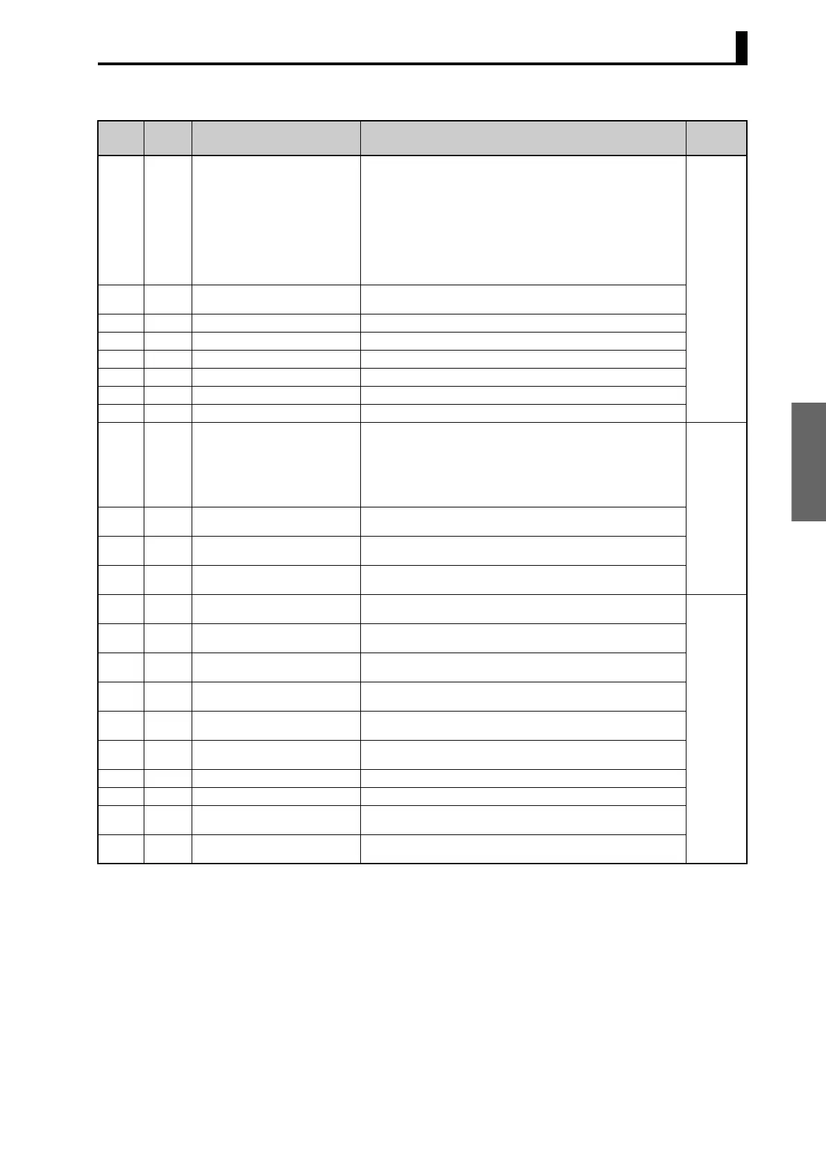
3.1 Variable Area (Setting Range) List
3-9
Note 1: Not displayed on the Controller display when Alarm 3 is not assigned to the output.
Note 2: The setting (monitor) range depends on the transfer output type setting. (See the setting data list for details.)
Note 3: This parameter can be set only for ON/OFF control.
Variable
type
Address Parameter name Setting (monitor) value Level
C3 (83) 0036 PV Change Color H'00000000 (0): Orange
H'00000001 (1): Red
H'00000002 (2): Green
H'00000003 (3): Red to green: When ALM1 is ON
H'00000004 (4): Green to red: When ALM1 is ON
H'00000005 (5): Red to green to red: Within PV stable band: Green
Outside stable band: Red
H'00000006 (6): Green to orange to red: Within PV stable band: Orange
Outside stable band: Green, red
H'00000007 (7): Orange to green to red: Within PV stable band: Green
Outside stable band: Orange, red
Advanced
function
setting
C3 (83) 0037 PV Stable Band Temperature: H'00000001 to H'00007E90 (0.1 to 3240.0)
Analog: H'00000001 to H'0000270F (0.01 to 99.99)
C3 (83) 0038 Alarm 1 ON Delay H'00000000 to H'000003E7 (0 to 999)
C3 (83) 0039 Alarm 2 ON Delay H'00000000 to H'000003E7 (0 to 999)
C3 (83) 003A Alarm 3 ON Delay (See note 1.) H'00000000 to H'000003E7 (0 to 999)
C3 (83) 003B Alarm 1 OFF Delay H'00000000 to H'000003E7 (0 to 999)
C3 (83) 003C Alarm 2 OFF Delay H'00000000 to H'000003E7 (0 to 999)
C3 (83) 003D Alarm 3 OFF Delay (See note 1.) H'00000000 to H'000003E7 (0 to 999)
C3 (83) 003E Transfer Output Type H'00000000 (0): OFF
H'00000001 (1): Set point
H'00000002 (2): Set point during SP ramp
H'00000003 (3): PV
H'00000004 (4): MV monitor (heating)
H'00000005 (5): MV monitor (cooling)
H'00000006 (6): Valve opening
Initial set-
ting
C3 (83) 003F Transfer Output Upper Limit H'FFFFF831 to H'0000270F (
−1999 to 9999)
H'FFFFB1E1 to H'00007E90 (
−19999 to 32400) (See note 2.)
C3 (83) 0040 Transfer Output Lower Limit H'FFFFF831 to H'0000270F (
−1999 to 9999)
H'FFFFB1E1 to H'00007E90 (
−19999 to 32400) (See note 2.)
C3 (83) 0041 Linear Current Output H'00000000 (0): 4 to 20 mA
H'00000001 (1): 0 to 20 mA
C3 (83) 0042 Input Shift Type H'00000000 (0): Temperature input 1-point shift
H'00000001 (1): Temperature input 2-point shift
Advanced
function
setting
C3 (83) 0043 MV at Stop and Error Addition H'00000000 (0): OFF
H'00000001 (1): ON
C3 (83) 0044 Auto/Manual Select Addition H'00000000 (0): OFF
H'00000001 (1): ON
C3 (83) 0045 RT H'00000000 (0): OFF
H'00000001 (1): ON
C3 (83) 0046 HS Alarm Use H'00000000 (0): OFF
H'00000001 (1): ON
C3 (83) 0047 HS Alarm Latch H'00000000 (0): OFF
H'00000001 (1): ON
C3 (83) 0048 HS Alarm Hysteresis H'00000001 to H'000001F4 (0.1 to 50.0)
C3 (83) 0049 LBA Detection Time (See note 3.) H'00000000 to H'0000270F (0 to 9999)
C3 (83) 004A LBA Level Temperature: H'00000001 to H'00007E90 (0.1 to 3240.0)
Analog: H'00000001 to H'0000270F (0.01 to 99.99)
C3 (83) 004B LBA Band Temperature: H'00000000 to H'00007E90 (0.0 to 3240.0)
Analog: H'00000000 to H'0000270F (0.00 to 99.99)
 Loading...


