2.2 Structure of Command Text
2-7
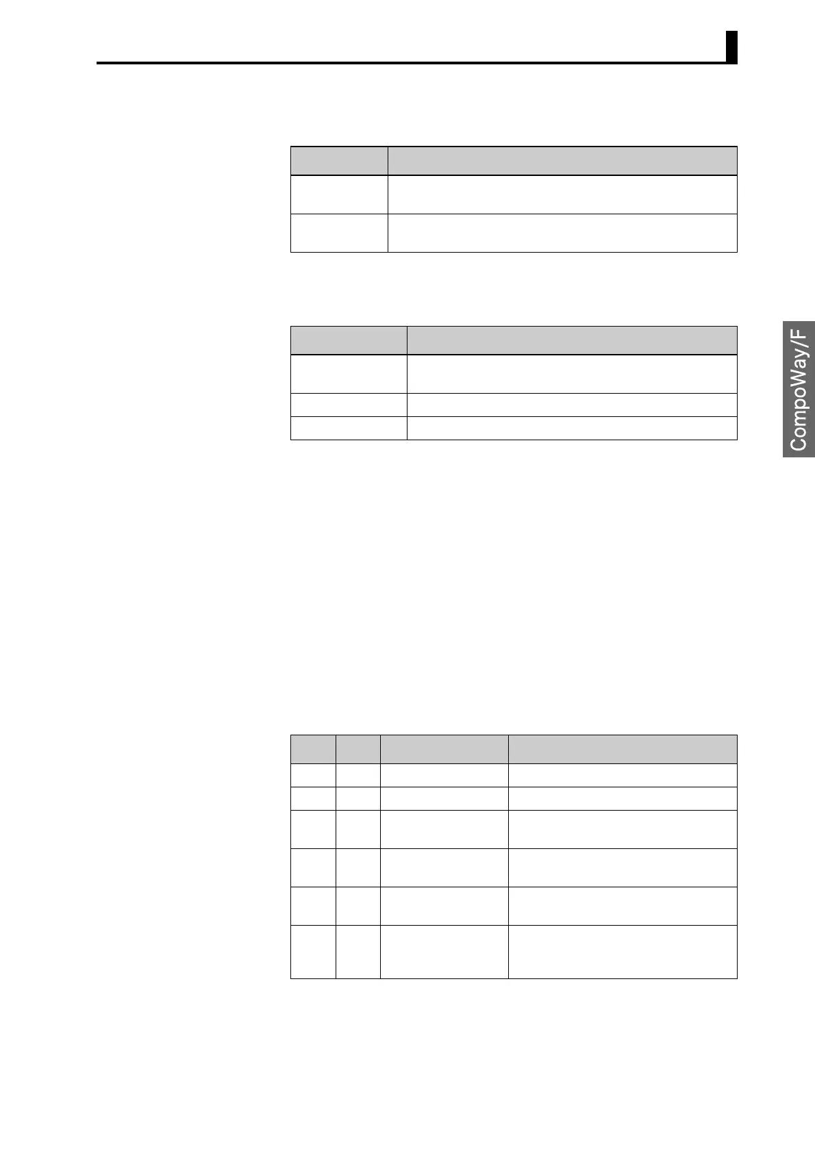
The following table summarizes setup areas 0 and 1.
The variable type is converted to 2-byte ASCII and loaded to the frame.
The following table shows the available variable types.
* Setup area 1 has no read-only parameters, so there is no variable
type “C2.”
■ Addresses An address is appended to each of the variable types. Express
addresses in 2-byte hexadecimal and append them for the specified
access size.
■ Number of Elements
The number of elements is expressed in 2-byte hexadecimal. Specify
the number of elements within the range “0 to 2.”
For example, when the number of elements is “0002,” this specifies two
items of data from the address.
■ List of Services
Area Description
Setup area 0 This area groups together the protect, manual control, opera-
tion, and adjustment levels.
Setup area 1 This area groups together the initial setting, communications
setting, advanced function setting, and calibration levels.
Variable type Description
C0 Double-word data. R/O (read only) parameter for setup
area 0.
C1 Double-word data. R/W parameter for setup area 0.
C3 Double-word data. R/W parameter for setup area 1.
MRC SRC Name of service Processing
01 01 Read Variable Area This service reads from variable areas.
01 02 Write Variable Area This service writes to variable areas.
05 03 Read Controller
Attributes
This service reads the model number
and communications buffer size.
06 01 Read Controller Sta-
tus
This service reads the operating sta-
tus.
08 01 Echoback Test This service performs an echoback
test.
30 05 Operation Com-
mand
This service performs operations such
as executing/stopping AT (auto-tuning)
and moving to Setup Area 1.