Temperature Controllers E5CSZ 3
■ Characteristics
Note: 1. The following exceptions apply to thermocouples.
• L: ±2°C ±1 digit max.
2. The following exceptions apply to platinum resistance thermometers.
Input set values 0, 1, 2, 3 for E5CSZ: 0.5% FS ±1 digit max.
Input set value 1 for E5CSZ: 0.5% FS ±1 digit max.
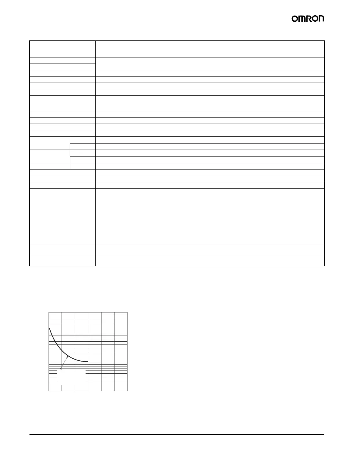
■ Electrical Life Expectancy Curve for Relays (Reference Values)
Setting accuracy Thermocouple (See note 1.): (±0.5% of indication value or ±1°C, whichever is greater) ±1 digit max.
Platinum resistance thermometer (See note 2.): (±0.5% of indication value or ±1
°C, whichever is greater) ±1 digit max.
Indication accuracy
(ambient temperature of 23
°C)
Influence of temperature Thermocouple inputs: (±1% of PV or ±4
°C, whichever is greater) ±1 digit max.
Platinum resistance thermometer inputs: (±1% of PV or ±2
°C, whichever is greater) ±1 digit max.
Influence of voltage
Hysteresis (for ON/OFF control) 0.1% FS for multi-input (thermocouple/platinum resistance thermometer) models
Proportional band (P) 1 to 999
°C (automatic adjustment using auto-tuning/self-tuning)
Integral time (I) 1 to 1,999 s (automatic adjustment using auto-tuning/self-tuning
Derivative time (D) 1 to 1,999 s (automatic adjustment using auto-tuning/self-tuning)
Alarm output range Absolute-value alarm: Same as the control range
Other: 0% to 100% FS
Alarm hysteresis: 0.2
°C or °F (fixed)
Control period 2/20 s
Sampling period 500 ms
Insulation resistance 20 M
Ω min. (at 500 VDC)
Dielectric strength 2,000 VAC, 50/60 Hz for 1 min between current-carrying terminals of different polarity
Vibration
resistance
Malfunction
10 to 55 Hz, 20 m/s
2
for 10 min each in X, Y, and Z directions
Destruction 10 to 55 Hz, 0.75-mm single amplitude for 2 hr each in X, Y, and Z directions
Shock resistance Malfunction
100 m/s
2
min., 3 times each in 6 directions
Destruction
300 m/s
2
min., 3 times each in 6 directions
Life expectancy Electrical 100,000 operations min. (relay output models)
Weight Approx. 120 g (Controller only)
Degree of protection Front panel: Equivalent to IP50; Rear case: IP20; Terminals: IP00
Memory protection EEPROM (non-volatile memory) (number of writes: 1,000,000)
EMC EMI Radiated: EN 55011 Group 1 Class A
EMI Conducted: EN 55011 Group 1 Class A
ESD Immunity: EN 61000-4-2: 4 kV contact discharge (level 2)
8 kV air discharge (level 3)
Radiated Electromagnetic Field Immunity: EN 61000-4-3: 10 V/m (80-1000 MHz, 1.4-2.0 GHz amplitude modulated) (level 3)
10 V/m (900 MHz pulse modulated)
Conducted Disturbance Immunity: EN 61000-4-6: 3 V (0.15 to 80 MHz) (level 2)
Noise Immunity (First Transient Burst Noise): EN 61000-4-4
Burst Immunity: 2 kV power-line (level 3), 1 kV I/O signal-line (level 3)
Surge Immunity: EN 61000-4-5: Power line: Normal mode 1 kV; Common mode 2 kV
Output line (relay output): Normal mode 1 kV; Common mode 2 kV
Voltage Dip/Interrupting Immunity: EN 61000-4-11 0.5 cycle, 100% (rated voltage)
Approved standards UL 61010C-1 (listing)
CSA C22.2 No.1010-1
Conformed standards EN 61326, EN 61010-1, IEC 61010-1
VDE 0106 Part 100 (finger protection), when the terminal cover is mounted.
500
300
100
50
30
10
5
3
1
0123456
Switching current (A)
Life (
×
10
4
operations)
E5CSZ
250 VAC, 30 VDC
(resistive load)
cosφ = 1