Temperature Controllers E5CSZ 5
External Connection Diagram
Note: 1. The voltage output (12 VDC, 21 mA) is not electrically isolated from the internal circuits. When using a grounding thermocouple, do not
connect output terminals 1 or 2 to ground. Otherwise, unwanted current paths will cause measurement errors.
2. Models with 100 to 240 VAC and 24 VAC/VDC are separate. Models using 24 VDC have no polarity.
3. The number of alarm outputs (none or 1) depends on the model.
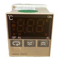
Nomenclature
E5CSZ Models with Terminal Blocks
8
9
10
7
6
3
4
5
2
11
2
1
2
3
4
5
12 VDC,
21 mA
Alarm output
Alarm output 1 (See note 3.
Relay output
models
Voltage output
models
(See note 1.)
Thermocouple/
platinum resistance thermometer multi-input
100 to 240 VAC, 50/60 Hz
(24 VAC/VDC)
(See note 2.)
A
B
B
Thermocouple
input
Relay outputVoltage output
Platinum resistance
thermometer input
E5CSZ
Output indicator
Alarm indicators
Temperature display
Up Key
Down Key
Deviation indicators
Mode indicators
Mode Key
Lock Release Key