E5jK-T
E5jK-T
24
Transfer Output
Connect transfer output (TRSF) to terminal numbers 29 and 30. The internal equalizing circuit for transfer output is as follows:
30
29
4 to 20mA
L
+
–
T
ransfer output specifications are as follows: 4 to 20 mA DC,
Permissible load impedance: 600
Ω
max.,
Resolution: Approx. 2,600
Communications
Terminal
numbers 18 to 20, 31 and 32 can be used only on Controllers with Communications Units (E53-AK01/02/03). For details on wiring,
refer
to
Chapter 6, Using the Communications Function
in the
E5AK-T/E5EK-T/E5CK-T User’
s Manual (H88/H89/H90)
.
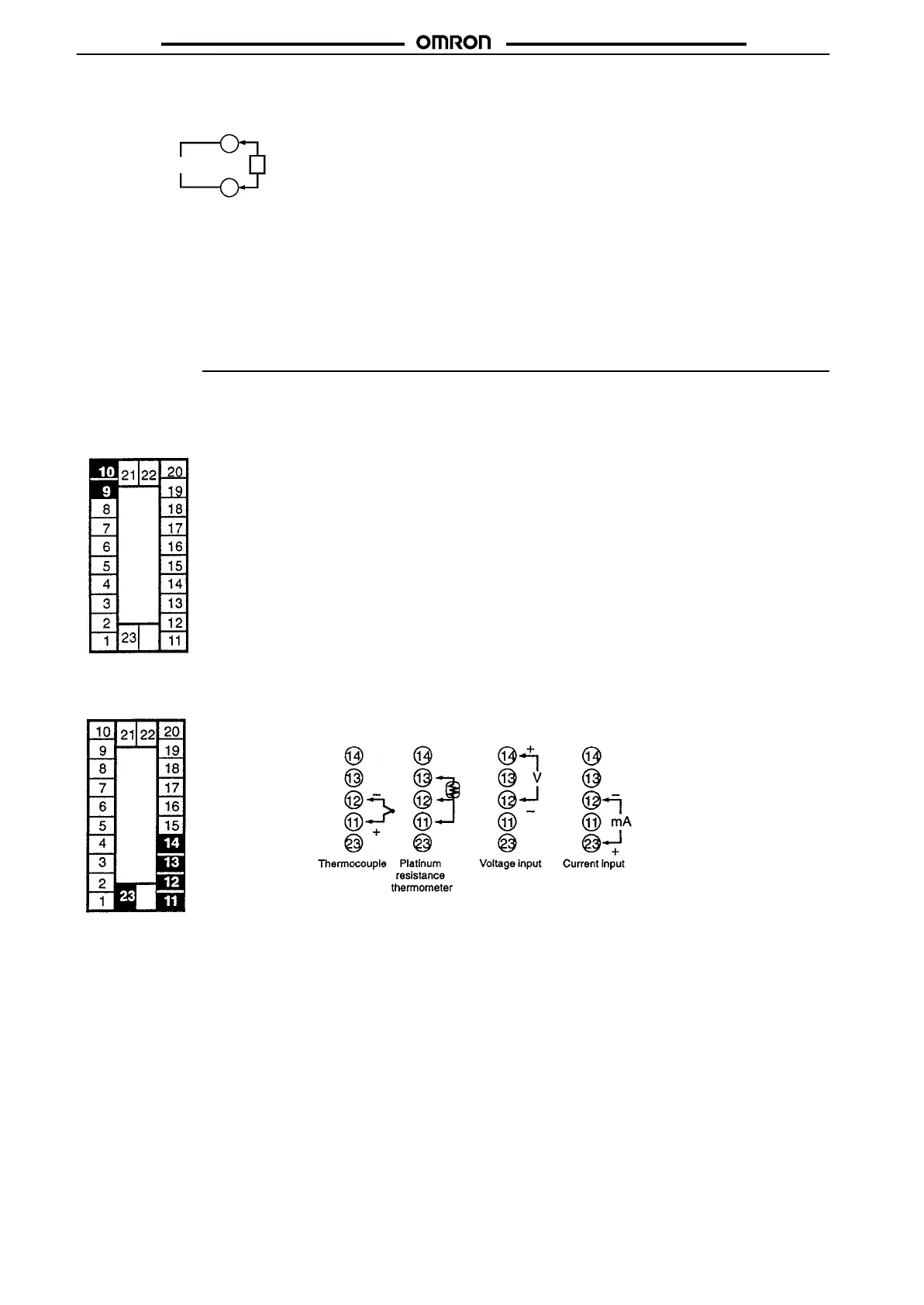
E5EK Wiring
In
the following wiring diagrams, the left side of the terminal numbers indicate the inside of the Controller
.
Power Supply
Input 100 to 240 V
AC or 24 V
AC/DC to terminal numbers 9 and 10 according to the specifications.
Sensor Input
Connect the sensor input to terminal numbers 1
1 to 14 and 23 as follows according to the input type.