E5jK-T
E5jK-T
13
Setup
Note:
Always turn OFF the power supply to the Digital Controller before changing any switch settings.
Settings (E5AK/E5EK)
On
a standard model, set up the Output Units for control outputs 1
and
2 before mounting the Controller
.
On
a position-proportional model, the Relay Output Unit is already
set.
Therefore, this setup operation
is unnecessary
. (Do not replace
with
other Output Units.)
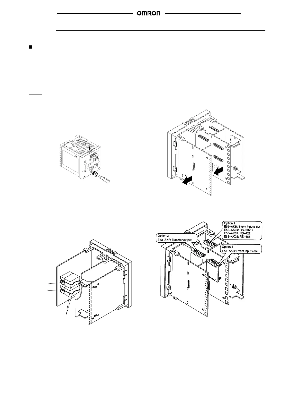
When
setting up the Output Units, draw out
the internal mechanism
from the housing and insert the Output Units into the sockets for
control
outputs 1 and 2.
E5AK
Draw-out
When drawing out the internal mechanism from the housing, pre-
pare
a Phillips screwdriver matched to the size
of the screw on the
lower
part of the front panel.
1. Press
down on
the hook on the top of the front panel, and turn
the
Phillips screwdriver to the left to loosen the screw on the
lower
part of the front panel.
Hook
2. Draw out the internal mechanism towards you holding both
sides
of the front panel.
Setting Up the Output Unit
• Before Setup
Check the type of the Output Unit you are about to set up.
• Procedure
1. Check
the positions of the sockets you are about
to insert the
Output
Units into as shown in the following diagram.
OUT2
OUT1
Bracket
2. Insert the Output Unit for control output 1 into the socket
“OUT1” and the Output Unit for control output 2 into the
socket “OUT2.”
3. Fasten the Output Units with the bracket (accessory).
Setting Up the Option Unit
• Before Setup
Check the type of the Option Unit you are about to set up.
• Procedure
1. Remove the power board and option boards in the order
shown
in the following diagram.
2. Insert
the
Option Units into the sockets for options 1 to 3. The
following
diagram shows the relationship between the Option
Units
and mounting positions.
3. Mount the Option Boards and the power board in the order
shown.