E5jK-T
E5jK-T
39
Precautions
WARNING
Do not touch the terminals while the power is ON.
This may cause an electric shock.
General Precautions
Be
sure to observe these precautions to ensure safe use.
• Do
not use the product in places where explosive or flammable
gases
may be present.
•
Never disassemble, repair or modify the product.
• T
ighten the terminal screws properly
.
•
Use the specified size of solderless terminals for wiring.
•
Use the product within the rated supply voltage.
•
Use the product within the rated load.
• The life expectancy of the output relay varies considerably
according
to its switching capacity and operating conditions. Be
sure
to use the output relay within its rated load and electrical life
expectancy.
If
the output relay is used beyond its life expectancy
,
its
contacts may become fused or burned.
Correct Use
If you remove the Controller from its case, never touch nor apply
shock
to the electronic parts inside.
Do
not cover the E5
jK-T
. (Ensure suf
ficient space around the Con
-
troller
to allow heat radiation.)
Do not use the Controller in the following places:
• Places subject to icing, condensation, dust, corrosive gas
(especially
sulfide gas or ammonia gas).
•
Places subject vibration and large shocks.
•
Places subject to splashing liquid or oil atmosphere.
•
Places subject to intense temperature changes.
•
Places subject to heat radiation from a furnace.
Be sure to wire properly with correct polarity of terminals.
When
wiring input or output lines to the Controller
, keep the follow
-
ing
points in mind to reduce the influence from inductive noise:
• Allow adequate space between the high voltage/current power
lines
and the input/output lines.
• Avoid parallel or common wiring with high voltage sources and
power lines carrying large currents.
• Using
separating pipes, ducts, and shielded line is also useful
in
protecting
the Controller
, and its lines from inductive noise.
Cleaning: Do not use paint thinner or organic solvents. Use stan-
dard
grade alcohol to clean the product.
Use
a voltage (100 to 240 V
AC at 50/60 Hz, or 24 VDC). At power
ON, the prescribed voltage level must be attained within two
seconds.
Allow as much space as possible between the Controller and
devices that generate a powerful high frequency (high-frequency
welders, high-frequency sewing machines, etc.) or surge. These
devices
may cause malfunctions.
If
there is a large power-generating peripheral device and any of its
lines
near the Controller
, attach a surge suppressor or noise filter
to
the
device to stop the noise af
fecting the Controller system. In par
-
ticular,
motors, transformers, solenoids and magnetic coils have
an
inductance component, and therefore can generate very strong
noise.
When
mounting a noise filter on the
power supply to the Controller
,
be sure to first check the filter’s voltage and current capacity, and
then
mount the filter as close as possible to the Controller
.
Use within the following temperature and humidity ranges:
• T
emperature: –10
°
C to 55
°
C (with no icing or condensation)
Humidity: 35% to 85% (with no icing or condensation)
If the Controller is installed inside a control board, the ambient
temperature must be kept to under 55°C, including the
temperature
around the Controller
.
If
the Controller is subjected to heat radiation, use a fan to cool
the surface of the Controller to under 55
°C.
Store within the following temperature and humidity ranges:
• T
emperature: –25
°
C to 65
°
C (with no icing or condensation)
Humidity: 35% to 85% (with no icing or condensation)
Never place heavy objects on, or apply pressure to the Controller
that
may cause it to deform and deteriorate during use or storage.
A
void using the Controller in places near a radio, television set, or
wireless installing. These devices can cause radio disturbances
which adversely af
fect the performance of the Controller
.
Mounting
The dimensions of the Digital Controller conform to DIN 43700.
Recommended
panel thickness is 1
to 8 mm (1 to 5 mm for E5CK).
Mount
the Unit horizontally
.
Connection
To
reduce inductive noise influence, the lead wires connecting the
input
type to the Digital Controller must be separated from the power
lines
and load lines.
Use the specified compensating conductors for thermocouples.
Use lead wires having a small resistance for platinum resistance
thermometers.
Connection Example
Wire
the terminals of the Unit using solderless terminals.
The
tightening torque applied to the terminal screws of the Unit must
be
approximately 0.78 N
S
m or 8 kgf
S cm.
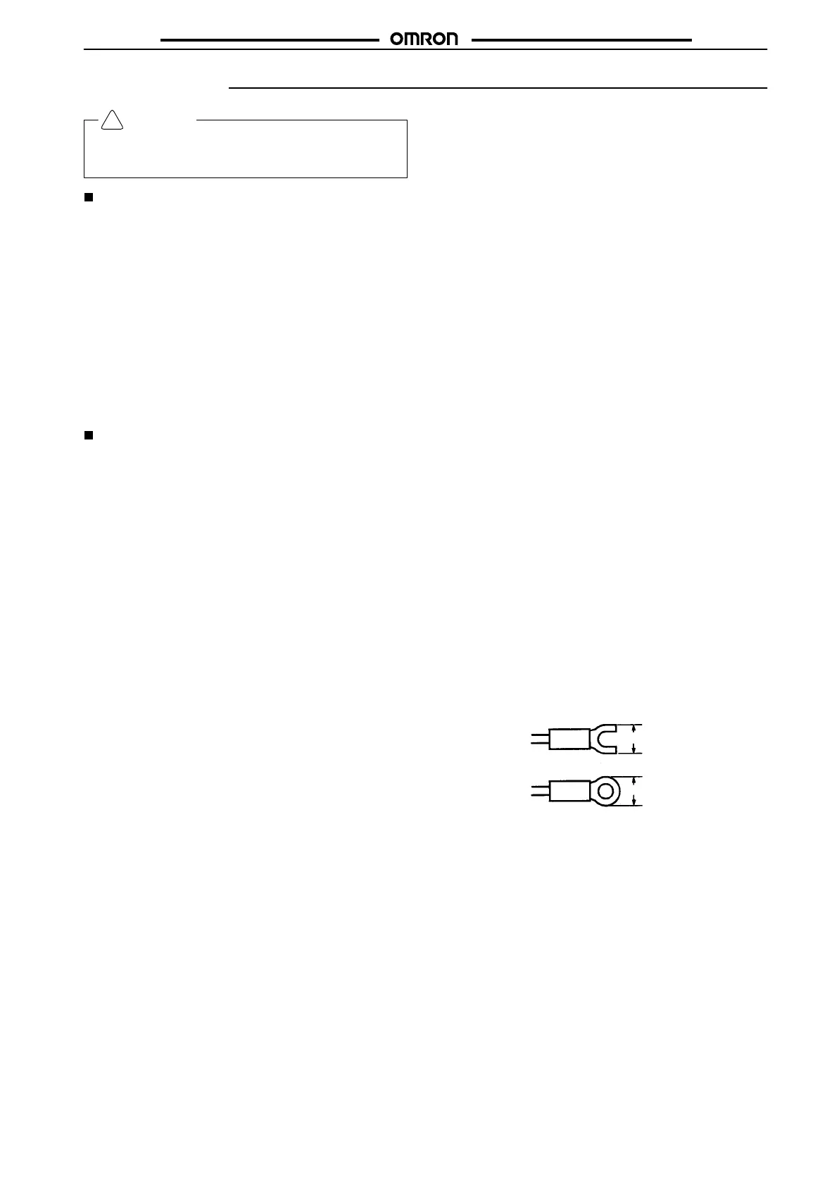
Use the following type of solderless terminals for M3.5 screws.
7.2
mm max.
7.2 mm max.
!
 Loading...


