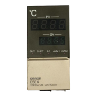
Do you have a question about the Omron E5EX–H and is the answer not in the manual?
| Brand | Omron |
|---|---|
| Model | E5EX–H |
| Category | Temperature Controller |
| Language | English |
Highlights advanced PID control, heater burnout detection, sensor/range selection, and accuracy.
Details model numbers for controllers, output units, and current transformers.
Lists temperature ranges for various thermocouple and resistance thermometer inputs.
Details supply voltage, power consumption, input types, operating modes, and approved standards.
Specifies ratings for Relay Output, SSR Output, and Voltage Output Units.
Details maximum continuous heater current, dielectric strength, vibration, and weight.
Covers setting/indication accuracy, PID parameters, response times, and environmental ratings.
Provides expected operational life for relay and SSR output units.
Details max heater current, indication accuracy, setting range, and min detectable ON time.
Illustrates physical dimensions for the temperature controller and current transformers.
Shows panel cutout dimensions and side-by-side mounting guidelines.
Identifies indicators, keys, and displays on the front panel of the controller.
Guide to accessing and setting internal switches for configuration.
Details how to set the temperature sensor type using DIP switch SW206.
Explains how to select operating modes like ON/OFF or PID using DIP switch SW201.
Describes selecting various alarm modes (upper-limit, lower-limit, event, proportional) via SW205.
Explains navigating through levels 0, 1, and 2 to set or monitor parameters.
Details setting parameters like alarm values, PID constants, and input shift in Level 0.
Describes the function of the protection switch for write-protecting settings.
How to set alarm values using the SV display and up/down keys.
Adjusting the proportional band (P constant) for control.
Adjusting the integral time (I constant) for control.
Adjusting the derivative time (D constant) for control.
Configuring input shift to adjust displayed temperature values.
Allows setting temperature range limits, control period, hysteresis, and heater burnout alarm.
Procedure for setting the heater burnout alarm value.
Defining the lower and upper limits for the temperature setting range.
Configuring the control period for PID or ON/OFF control.
Details setting temperature limits, hysteresis, heater current, and burnout alarm for ON/OFF mode.
Adjusting hysteresis for ON/OFF control action.
Allows monitoring of control output, selected sensor, and alarm modes.
Displays the control output amount as a percentage (0.0% to 100.0%).
Identifies the currently selected temperature sensor type.
Displays the currently selected alarm mode.
Initial steps for starting temperature control after parameter input.
Details the process of automatically tuning PID constants for optimal control.
Explains advanced PID control with two degrees of freedom for improved response.
Lists PV display error messages, their causes, and control/alarm outputs.
Provides wiring diagrams for connecting sensors, transformers, and output devices.
Advises on mounting, environmental conditions, and avoiding noise.
Details mounting dimensions and fixture tightening instructions.
Shows examples of connecting using solderless terminals and solder-dipped leads.
Recommends separating sensor wires from power lines to reduce noise.
 Loading...