10 Basic type digital temperature controller E5GN
USB-Serial Conversion Cable
Note: A driver must be installed in the personal computer. Refer to
installation information in the operation manual for the
Conversion Cable.
Communications Specifications
*
The baud rate, data bit length, stop bit length, and vertical parity can be
individually set using the Communications Setting Level.
Current Transformer (Order Separately)
Ratings
Heater Burnout Alarms, SSR Failure
Alarms, and Heater Overcurrent Alarms
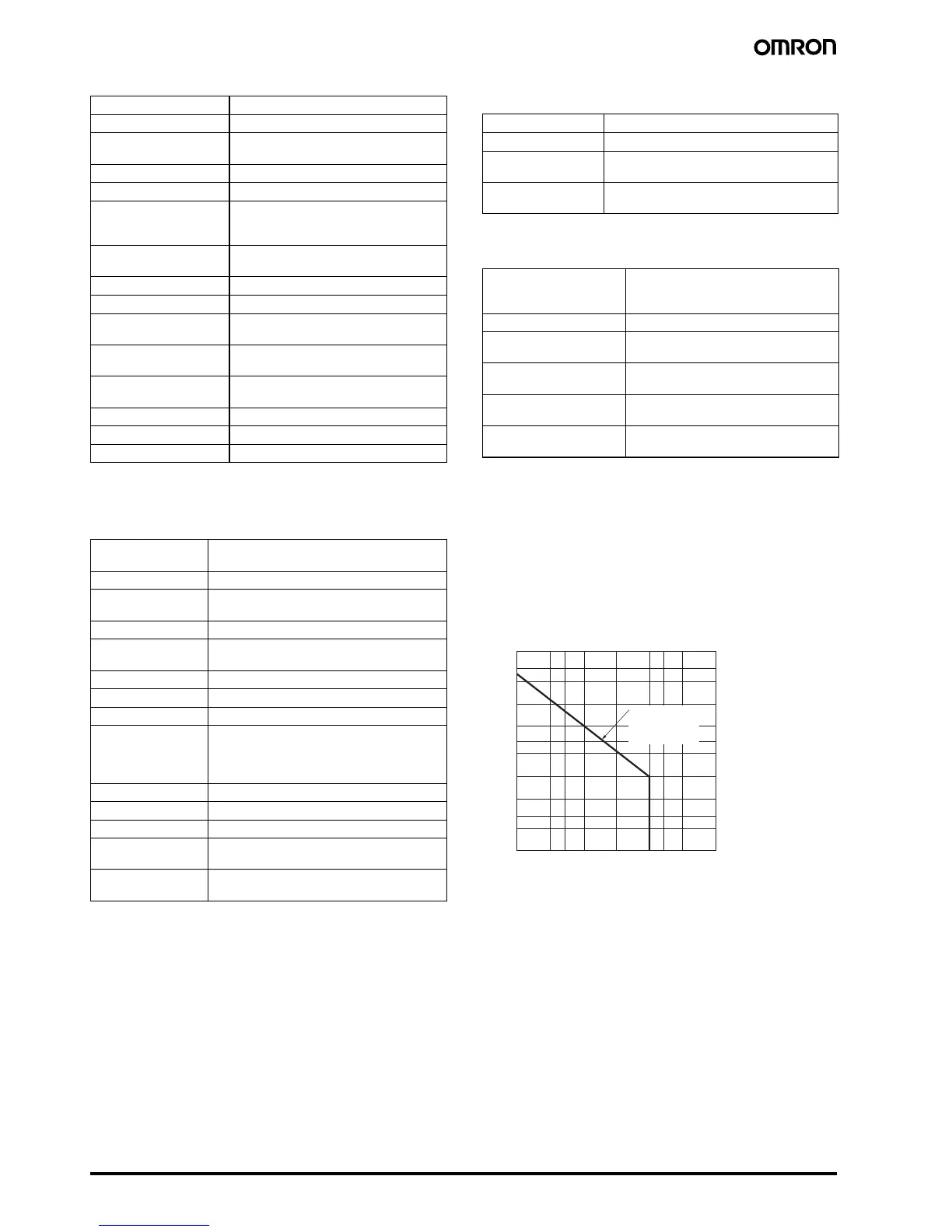
Electrical Life Expectancy Curve for
Relays (Reference Values)
Applicable OS Windows 2000, XP, or Vista
Applicable software CX-Thermo version 4 or higher
Applicable models
E5AN/E5EN/E5CN/E5CN-U/E5AN-H/
E5EN-H/E5CN-H/E5GN
USB interface standard Conforms to USB Specification 1.1.
DTE speed 38400 bps
Connector
specifications
Computer: USB (type A plug)
Temperature Controller: Setup Tool port
(on bottom of Controller)
Power supply
Bus power (Supplied from USB host
controller.)
Power supply voltage 5 VDC
Current consumption 70 mA
Ambient operating
temperature
0 to 55°C (with no condensation or icing)
Ambient operating
humidity
10% to 80%
Storage temperature
−20 to 60°C (with no condensation or
icing)
Storage humidity 10% to 80%
Altitude 2,000 m max.
Weight Approx. 100 g
Transmission line
connection method
RS-485: Multipoint
RS-232C: Point-to-point
Communications RS-485 (two-wire, half duplex), RS-232C
Synchronization
method
Start-stop synchronization
Protocol CompoWay/F, SYSWAY, or Modbus
Baud rate
1200, 2400, 4800, 9600, 19200, 38400, or
57600 bps
Transmission code ASCII
Data bit length* 7 or 8 bits
Stop bit length* 1 or 2 bits
Error detection
Vertical parity (none, even, odd)
Frame check sequence (FCS) with SYSWAY
Block check character (BCC) with
CompoWay/F or CRC-16 Modbus
Flow control None
Interface RS-485, RS-232C
Retry function None
Communications
buffer
217 bytes
Communications
response wait time
0 to 99 ms
Default: 20 ms
Dielectric strength 1,000 VAC for 1 min
Vibration resistance 50 Hz, 98 m/s
2
Weight
E54-CT1: Approx. 11.5 g,
E54-CT3: Approx. 50 g
Accessories
(E54-CT3 only)
Armatures (2)
Plugs (2)
CT input
(for heater current
detection)
Models with detection for single-phase
heaters: One input
Maximum heater current 50 A AC
Input current indication
accuracy
±5% FS ±1 digit max.
Heater burnout alarm
setting range
*1
*1.
For heater burnout alarms, the heater current will be measured when the
control output is ON, and the output assigned to the alarm 1 function will turn
ON if the heater current is lower than the set value (i.e., heater burnout
detection current value).
0.1 to 49.9 A (in units of 0.1 A)
Minimum detection ON time: 100 ms
SSR failure alarm
setting range
*2
*2.
For SSR failure alarms, the heater current will be measured when the control
output is OFF, and the output assigned to the alarm 1 function will turn ON
if the heater current is higher than the set value (i.e., SSR failure detection
current value).
0.1 to 49.9 A (in units of 0.1 A)
Minimum detection OFF time: 100 ms
Heater overcurrent
alarm setting range
*3
*3.
For heater overcurrent alarms, the heater current will be measured when the
control output is ON, and the output assigned to the alarm 1 function will turn
ON if the heater current is higher than the set value (i.e., heater overcurrent
detection current value).
0.1 to 49.9 A (in units of 0.1 A)
Minimum detection ON time: 100 ms
500
300
200
100
50
30
20
10
5
3
2
1
0.1 0.2 0.50.3 1 2 3 5 10
E5GN
250 VAC, 30 VDC
(resistive load)
cosφ = 1
Switchin
 Loading...