10
Operation
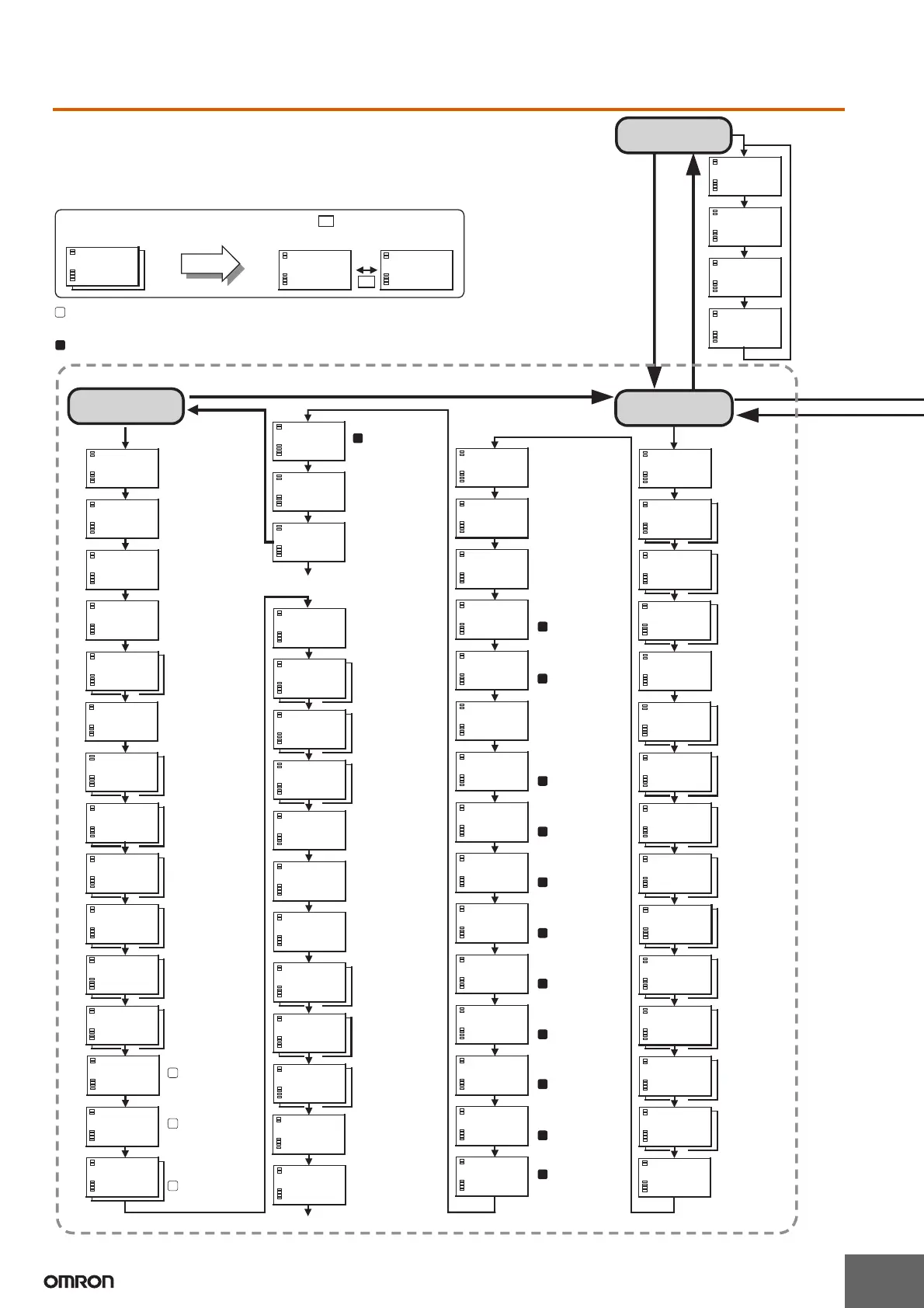
Initial setting value
CH
CH
L
Key 1 s min.
CH
L Key
L Key
A
P
A
A
A
A
A
A
A
A
A
A
A
Top of initial setting level
P
P
A
P
Top of advanced function setting level
CH
ch2: ch1:
Advanced function
setting level
Move to
the
advanced
function
setting
level by
entering
the
password
"−169".
Multi-SP used
SP ramp set
value
Parameter
initialize
Number of
multi-SP
used
Event input
allocation
Standby sequence
reset
Alarm 1 open
in alarm
Alarm 1
hysteresis
Alarm 2 open
in alarm
Alarm 2
hysteresis
Alarm 3 open
in alarm
Alarm 3
hysteresis
HBA used
Heater Burnout Latch
Heater burnout
hysteresis
Operation after
power ON
OUT1 transfer
output upper limit
OUT1 transfer
output lower limit
Control output 2
allocation
Auxiliary output 1
allocation
Auxiliary output 2
allocation
Auxiliary output 3
allocation
Auxiliary output 4
allocation
OUT2 transfer
output upper limit
OUT2 transfer
output lower limit
SUB3 transfer
output upper limit
SUB3 transfer
output lower limit
SUB4 transfer
output upper limit
SUB4 transfer
output lower limit
Current output type
Input type
Scaling upper limit
Scaling lower limit
Decimal point
Temperature unit
PID control and
ON/OFF control
switching
Alarm 1 type
Alarm 2 type
Alarm 3 type
Control output 1
allocation
SP upper limit
SP lower limit
Control period
(heat)
Control period
(cool)
Direct/reverse
operation
in-h
100
1
0
in-h
100
10
in-h
100
0
alh1
0.2
C
1
0
alh2
0.2
C
1
0
hbu
on
u
0
hbl
off
u
0
mspu
off
u0
eV-m
1
u
0
M
M
M
M
M
M
a1lt
off
1
0
a2lt
off
1
0
a3lt
off
1
0
inf
0.0
1
0
pVad
off
u0
M
isdp
off
u0
init
off
u
0
eV
none
u0
rest
a
u
0
al1n
n-o
1
0
al2n
n-o
1
0
alfa
0.65
u
0
ol-h
105.0
1
0
ol-l
-5.0
1
0
sero
off
u
0
hbh
0.1
1
0
M
ot-2
0
u
0
M
amoV
0
u
0
sedu
3
u
0
M
istp
0
u
0
cjc
on
u
0
sprt
0
1
0
M
M
M
M
M
M
M
M
M
M
M
M
M
M
M
M
M
al3n
n-o
10
alh3
0.2
C
10
M
M
M
sub4
17
u
0
out2
5
u
0
M
sub1
2
u
0
M
sub2
7
u
0
M
sub3
12
u
0
M
tr1h
1300
u
0
M
cont
no
u
0
M
tr3h
1300
u
0
M
tr1l
-200
u0
M
tr2h
1300
u0
tr2l
-200
u
0
M
M
tr3l
-200
u
0
M
tr4h
1300
u
0
M
M
ot-1
0
u
0
tr4l
-200
u
0
in-l
0
1
0
dp
0
1
0
sl-h
1300
C
1
0
sl-l
- 200
C
1
0
cntl
onof
1
0
alt1
2
1
0
cp
2
10
alt2
2
1
0
in-t
0
u
0
in-h
100
1
0
d-u
c
u
0
alt3
2
1
0
c-cp
2
10
oreV
or-r
1
0
out1
0
u
0
M
M
M
M
M
M
M
M
M
M
M
M
M
M
M
len
7
u
0
sbit
2
u
0
prty
eVen
u
0
sdwt
20
u
0
M
M
M
M
2
M
Additional PV display
The display below indicates that
there is setting data for ch1 or ch2.
CH
Press the Button to switch
between the screens for ch1 and ch2.
: This symbol indicates setting data that is displayed only for models with pulse output.
("Models with pulse output" is used here to indicate models with voltage output or transistor output.)
: This symbol indicates setting data that is displayed only for models with analog output.
Communications
setting level
L Key
1 s max.
Communica-
tions data
length
Communica-
tions stop bit
Communica-
tions parity
Communica-
tions
response wait
time
Voltage output type
Sensor error
indicator used
Move to advanced
function setting level
α
MV upper limit
MV lower limit
Input digital filter
Additional
temperature input
shift value display
Temperature
input shift type
Alarm 1 latch
Alarm 2 latch
Alarm 3 latch
Input error output
Cold junction
compensating
method
The setting data that can be set from the E5ZN-SDL Setting Display Unit is shown below.
Depending on the protection settings and other factors, some settings may not be displayed.
A password is required to move to the advanced function setting level.
 Loading...


