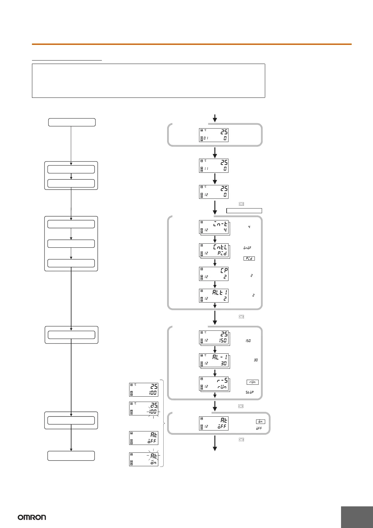
EasyManua.ls Logo

Omron E5ZN Series User Manual

Omron E5ZN Series
14 pages
To Next Page IconTo Next Page
To Previous Page IconTo Previous Page
Page #5 background imageLoading...
Page #5 background image
5
Typical Example 2
Input type: 4 T thermocouple 200 to 400°C
Control method: PID control
Calculate PID constants using AT (auto-tuning).
Alarm type: 2 upper limit
Alarm value 1: 30°C
Set point: 150°C
E5ZN unit number: 1
Channel number: 2
Check the alarm type.
Operation Level
Start operation
Set the channel number.
Set the unit number.
Set the control method.
Set the alarm type.
Set input specifications.
Power ON
Process
value/set point
Input type
For ON/OFF
control
Control period (OUT1)
(unit: seconds)
For PID
control
Control stops.
Operation Level
Initial Setting Level
Press the Key for at least 3 s.
Set the unit number using the UNIT Key.
AT ends and operation starts.
Initial Setting Level
Set the channel number using the CH Key.
Alarm 1 type
Press the . Key for at least one second.
Set to pid when PID control is used.
M
M
M
M
Power ON
Process value/
set point
To
operate
Alarm value 1
To stop
Operation level
M
M
M
PV/SP
After AT execution.
During AT execution.
SP will flash while AT
is being executed.
After AT execution.
During AT execution.
Press the Key (for less than 1 s).
To execute AT
Execute AT.
Adjustment Level
Press the Key for less than one second.
To stop AT
AT execution
Adjustment Level
(for PID control)
Use the U and
D Keys to set the
input type to 4.
Use the U and
D Keys to check
that the control is
PID.
Check the control
period.
Check the alarm
type.
Press the U and
D Keys to set the
set point to 150°C.
Press the U and
D Keys to set the
alarm value to
30°C.
Select "Run"
using the U and
D Keys.
Set to on to execute AT and
to off to stop AT.
Recommended settings: 20 s for a
relay output and 2 s for a voltage/
SSR output.
Setup Procedure

Other manuals for Omron E5ZN Series

Question and Answer IconNeed help?

Do you have a question about the Omron E5ZN Series and is the answer not in the manual?

Omron E5ZN Series Specifications

General IconGeneral
Control MethodPID, ON/OFF
Input TypeThermocouple, RTD, Analog
Output TypeRelay, Voltage, Current
Display TypeDigital LCD
Power Supply100 to 240 VAC, 24 VAC/VDC
CommunicationRS-485
Operating Temperature55°C
Operating Humidity25 to 85% RH (non-condensing)
Number of Control Outputs1

Summary

E5ZN Operation Nomenclature

Using Setting Switches

Unit Number Switch

Configures the unit number for controller identification on the host system.

Baud Rate

Sets the communication baud rate to match the host system.

Operation Indicators

Explains the meaning of the indicator lights on the front panel.

Mounting

Dimensions

Shows the physical dimensions of the Terminal Unit E5ZN-SCT24S and E5ZN-SCT18S.

Mounting Terminal Units Together

Details how to connect multiple Terminal Units using interlocking connectors.

Mounting to the DIN Track

Mounting the Controller

Step-by-step procedure for mounting the controller onto the DIN track.

Removing the Controller

Instructions on how to detach the controller from the DIN track.

Setup Guidance

Typical Example 1

Demonstrates a setup procedure for ON/OFF control with an upper limit alarm.

Setup Procedure

Guides through the step-by-step process of setting up the controller.

Typical Example 2

Setup Procedure

Illustrates the setup process for PID control with auto-tuning.

Using Copy Mode

Upload (Temperature Controller to Setting Display Unit)

Details the process of transferring settings from the controller to the display unit.

Download (Setting Display Unit to Temperature Controller)

Describes how to transfer settings from the display unit back to the controller.

Operating Procedure Overview

Description of Modes

Outlines the different operating modes and their functions.

Description of Modes

Protect Level

Mode for preventing parameter modification.

Operation Level

Default mode for monitoring PV, SP, MV, and alarms.

Adjustment Level

Mode for setting control values and offsets, including auto-tuning.

Initial Setting Level

Mode for specifying input type, control method, and alarm types.

Advanced Function Setting Level

Mode for advanced settings like MV limits and standby sequences.

Communications Setting Level

Mode for configuring communication settings with a host device.

Operation

Advanced function setting level

Details parameters available in the advanced function setting level.

Communications setting level

Details parameters available in the communications setting level.

Initial setting value

Lists parameters for initial setup, like input type and scaling.

Input Type

Output Assignments

Table showing default functions assigned to output terminals.

Resistance Thermometer Input

Specifies input types and ranges for resistance thermometers.

Thermocouple Input

Lists thermocouple types, ranges, and corresponding set values.

Alarm Type

Alarms 1 and 2

Details alarm types and output configurations for alarms 1 and 2.

Alarm 3

Details alarm types and output configurations for alarm 3.

Error Displays

Related product manuals