F3SJ-A
13
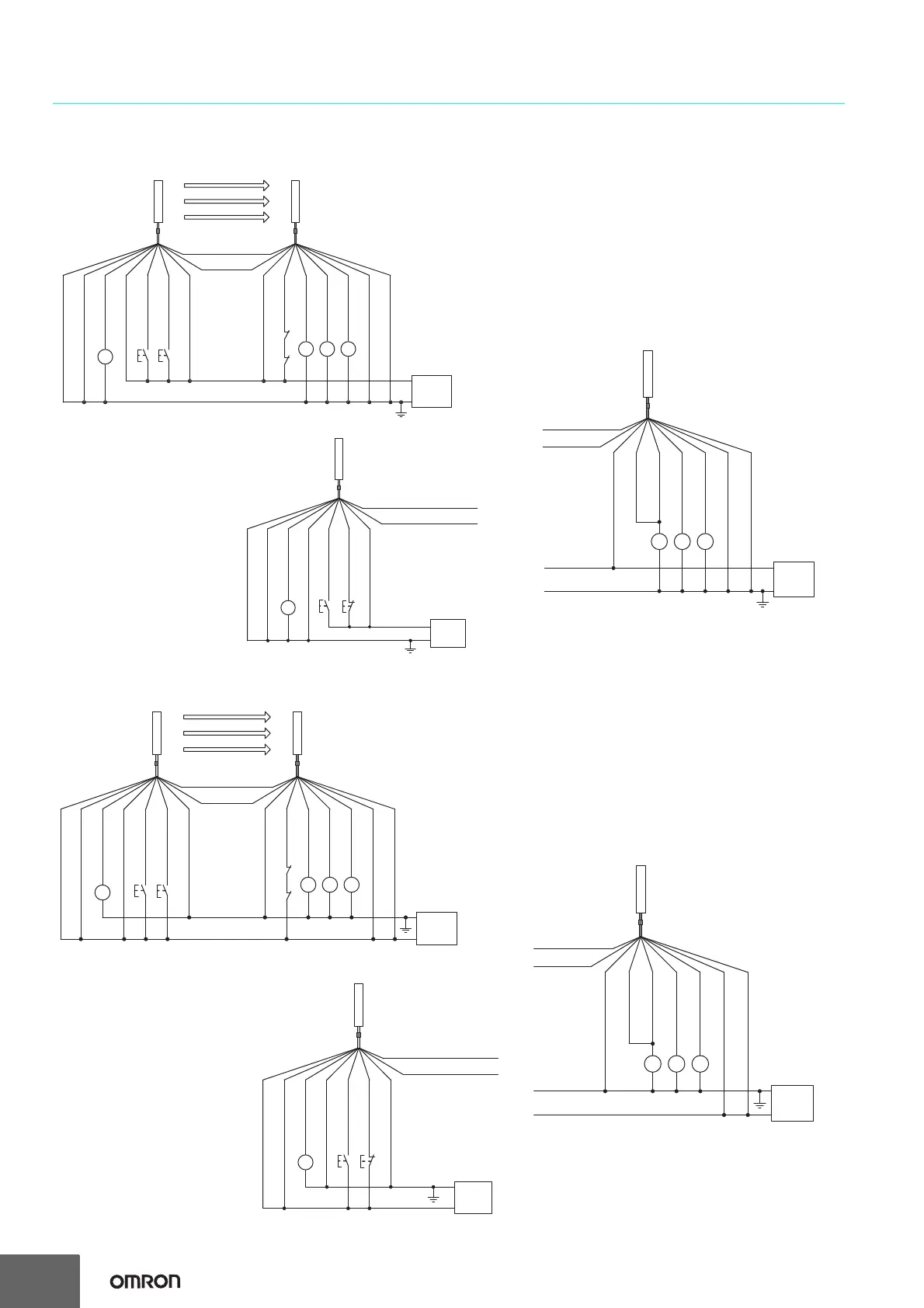
Connections
Basic Wiring Diagram
S1 S2
K2
K1
KM2
KM1
KM1 KM2
0 V
+24 VDC
*1. Use a switch for small loads
(input specifications: 24 V, 1.0 mA max.).
*2. F3SJ operates even when K1 and K2 are not connected.
S1 : External test switch (connect to 0 V if a switch is not required)
S2 :
Interlock/lockout reset switch
KM1, KM2 : Safety relay with force-guided contact (G7SA) or magnetic
contactor
K1, K2 : Load or PLC, etc. (for monitoring)
Auxiliary output 2 (Red)
Test input (Black)
Auxiliary output 1
(Yellow)
Safety output 1
(Black)
Power
supply
*2
*2
*1*1
Receiver
Emitter
Shield
Reset input (Yellow)
Shield
Interlock select input (White)
External device
monitoring input (Red)
0 V (Blue)
0 V (Blue)
(Gray) Communication line (+)
(Pink)
Communication
line (
−
)
+24 V (Brown)
+24 V (Brown)
Safety output 2
(White)
S1
*1*1
*2
S3
K2
S1
: External test switch
(connect to 0 V if a switch is not required)
S3 : Lockout reset switch
(connect to 24 V if
a
switch is not
required
)
K2
: Load or PLC, etc. (for monitoring)
Auxiliary output 2 (Red)
Test input (Black)
Emitter
Reset input (Yellow)
Shield
Interlock select input (White)
0 V (Blue)
+24 V (Brown)
0 V
+24 VDC
Power
supply
(Gray) Communication line (+)
(Pink) Communication line (−)
*1. Use a switch for small loads
(Input specifications: 24 V, 1.0 mA max.).
*2. F3SJ operates even when K2 is not connected.
KM1
KM2
K1
KM1, KM2 : Safety relay with force-guided contact (G7SA)
or magnetic contactor
K1
: Load or PLC, etc. (for monitoring)
* F3SJ can operate even if K1 is not connected.
If K1 is not required, connect auxiliary output 1
to external device monitoring input only.
*
Shield
0 V (Blue)
+24 V (Brown)
0 V
+24 VDC
Power
supply
(Gray)
Communication line (+)
(Pink)
Communication line (
−
)
Auxiliary output 1
(Yellow)
Safety output 1 (Black)
External device
monitoring input (Red)
Safety output 2 (White)
Receiver
Wiring when the external device monitoring
function will not be used
• Use a setting tool to set
the external device
monitoring functio
n to "Disabled."
• When using an auxiliary output 1 that has not been
changed (output operation mode is "control
output
data,"
and inverse of safety out
put signals is
"Enabled),
the external dev
ice monitoring function
will be disa
bled when auxiliary output 1 an
d the
external device monitoring input are co
nnect
ed as
sh
own below.
Wiring when using manual reset mode, external device monitoring
Wiring for auto reset mode
• The auto reset mo
de will be enabled
whe
n the emitter is wired as show
n
below.
S1 S2
K2
K1
KM2
KM1
KM1 KM2
0 V
+24 VDC
*1. Use a switch for small loads
(input specifications: 24 V, 1.0 mA max.).
*2. F3SJ operates even when K1 and K2 are not connected.
S1 : External test switch (connect to 24 V if a switch is not required)
S2 :
Interlock/lockout reset switch
KM1, KM2 : Safety relay with force-guided contact (G7SA) or magnetic
contactor
K1, K2 : Load or PLC, etc. (for monitoring)
Auxiliary output 2 (Red)
Test input (Black)
Auxiliary output 1
(Yellow)
Safety output 1
(Black)
Power
supply
*2
*2
*1*1
Receiver
Emitter
Shield
Reset input (Yellow)
Shield
Interlock select input (White)
External device
monitoring input (Red)
0 V (Blue)
0 V (Blue)
(Gray) Communication line (+)
(Pink)
Communication
line (-)
+24 V (Brown)
+24 V (Brown)
Safety output 2
(White)
S1 S3
K2
*1*1
*2
S1
: External test switch
(connect to 24 V if a switch is not required)
S3 : Lockout reset switch
(connect to 0 V if
a
switch is not
required
)
K2
: Load or PLC, etc. (for monitoring)
Auxiliary output 2 (Red)
Test input (Black)
Emitter
Reset input (Yellow)
Shield
Interlock select input (White)
0 V (Blue)
+24 V (Brown)
0 V
+24 VDC
Power
supply
(Gray) Communication line (+)
(Pink) Communication line (−)
*1. Use a switch for small loads
(Input specifications: 24 V, 1.0 mA max.).
*2. F3SJ operates even when K2 is not connected.
KM1
KM2
K1
KM1, KM2 : Safety relay with force-guided contact (G7SA)
or magnetic contactor
K1
: Load or PLC, etc. (for monitoring)
* F3SJ can operate even if K1 is not connected.
If K1 is not required, connect auxiliary output 1
to external device monitoring input only.
*
Shield
0 V (Blue)
+24 V (Brown)
0 V
+24 VDC
Power
supply
(Gray)
Communication line (+)
(Pink)
Communication line (
−
)
Auxiliary output 1
(Yellow)
Safety output 1 (Black)
External device
monitoring input (Red)
Safety output 2 (White)
Receiver
Wiring when using manual reset mode, external device monitoring
Wiring for auto reset mode
• The auto reset mode will be enabled wh
en the
emitter is wired as shown below.
Wiring
when the external device monitoring
function will not be used
• Use a setting tool to set the external device
monito
ring function to "Disabled."
• When using an auxiliary output 1 that has not be
en
changed (output operation mode is "safety output
data," an
d inverse of control ou
tput signals is
"Enabled), the
external dev
ice monitoring function
will be disabled when auxiliary output 1 and the
external device monitoring input are
connected
as
show
n below.

 Loading...


