F3SJ-A
14
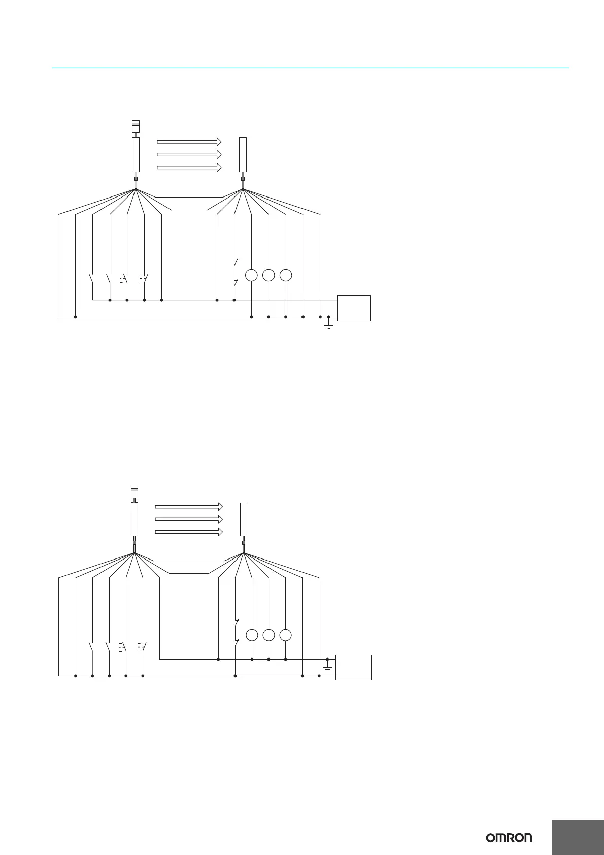
Basic Wiring Diagram for Muting System
*
1
*
5
*
5
*
1
*
2
*
3
*
4
KM2 KM1
K1
KM1
KM2
B1 A1 S1 S2
M1
*
4
*
4
Muting input 1
(White)
Muting input 2
(Red)
S1
: External test switch (connect to 24 V if a switch is not required)
S2
:
Lockout reset switch (connect to 0 V if a switch is not
required
)
A1 :
Contact by muting sensor A1
B1 :
Contact by muting sensor B1
KM1, KM2
: Safety relay with force-guided contact (G7SA) or magnetic contactor
K1
: Load or PLC, etc. (for monitoring)
M1 : Muting lamp
*1. Use a switch for small loads (input specifications: 24 V, 1.0 mA max.).
*2. When using the interlock function, this also functions as an interlock reset switch. (Must be set with a setting tool.)
*3. F3SJ operates even when K1 is not connected.
*4. Connect the muting lamp to either the external indicator output or auxiliary output 1 for the emitter or the receiver. When
connecting the muting lamp to auxiliary output 1, the parameter must be changed with a setting tool.
*5. Two-wire type muting sensor cannot be used.
0 V
+24 VDC
Test input (Black)
Auxiliary output 1
(Yellow)
Safety output 1
(Black)
Power
supply
Receiver
Emitter
Shield
Reset input (Yellow)
Shield
External device
monitoring input (Red)
0 V (Blue)
0 V (Blue)
(Gray)
Communication line (+)
(Pink)
Communication
line (-)
+24 V (Brown)
+24 V (Brown)
Safety output 2
(White)
*
4
*
4
*
4
*
1
*
5
*
5
*
1
*
2
*
3
KM2 KM1
K1
KM1
KM2
Muting input 1
(White)
Muting input 2
(Red)
B1 A1 S1 S2
S1
: External test switch (connect to 0 V if a switch is not required)
S2
:
Lockout reset switch (connect to 24 V if a switch is not
required
)
A1 :
Contact by muting sensor A1
B1 :
Contact by muting sensor B1
KM1, KM2
: Safety relay with force-guided contact (G7SA) or magnetic contactor
K1
: Load or PLC, etc. (for monitoring)
M1 : Muting lamp
*1. Use a switch for small loads (input specifications: 24 V, 1.0 mA max.).
*2. When using the interlock function, this also functions as an interlock reset switch. (Must be set with a setting tool.)
*3. F3SJ operates even when K1 is not connected.
*4. Connect the muting lamp to either the external indicator output or auxiliary output 1 for the emitter or the receiver. When
connecting the muting lamp to auxiliary output 1, the parameter must be changed with a setting tool.
*5. Two-wire type muting sensor cannot be used.
M1
0 V
+24 VDC
Test input (Black)
Auxiliary output 1
(Yellow)
Safety output 1
(Black)
Power
supply
Receiver
Emitter
Shield
Reset input (Yellow)
Shield
External device
monitoring input (Red)
0 V (Blue)
0 V (Blue)
(Gray)
Communication line (+)
(Pink)
Communication
line (-)
+24 V (Brown)
+24 V (Brown)
Safety output 2
(White)
Wiring when using muting and external device monitoring functions
[NPN Output]
When external device monitoring function is not required
• Use a setting tool to set the external device monitoring function to
"Disabled."
• When using an auxiliary output 1 that has not been chang
ed
(output operation mode is "
safety output data," and inverse o
f
contro
l output signals is "Enabled), the external device monitoring
function will be disabled when auxiliary output 1 and the external
device monitoring input are connected.
When external device monitoring function is not required
• Use a setting tool to set the external device monitoring function to
"Disabled."
• When using an auxiliary output 1 that has not been chang
ed
(output operation mode is "safety output data," and inverse of
contro
l output signals is "Enabled), the external device monitoring
function will be disabled when auxiliary output 1 and the external
device monitoring input are connected.
Wiring when using muting and external device monitoring functions

 Loading...


