F3SJ-A
15
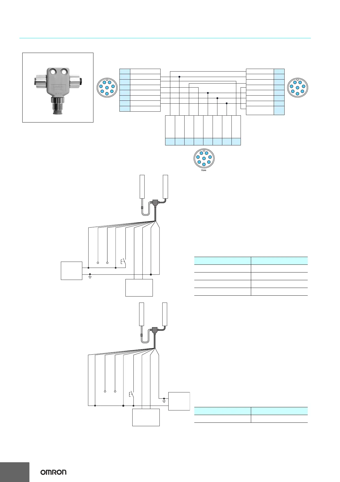
Wiring Diagram When Using Simple Wiring System
Note: When using the Simple Wiring Connector (F39-CN5), the following functions are not available.
• Manual Reset
• External Device Monitoring
• Auxiliary Outputs 1, 2
• Muting/Override
When using the setting tools, make sure to keep the settings in the factory default.
1
PIN No.
PIN No.
Emitter
Internal wiring of F39-CN5 simple wiring connector
1
2
3
4
5
6
7
8
Interlock select input
24 VDC
Test input
Reset input
Communication line (+)
Communication line (-)
0 V
Auxiliary output 2
Female Female
7
8
2
3
4
5
6
1
7
8
2
3
4
5
6
2
3
8
1
7
6
5
4
PIN No.Receiver
1
2
3
4
5
6
7
8
123 4567 8
Safety output 2
24 VDC
Safety output 1
Auxiliary output 1
Communication line (+)
Communication line (-)
0 V
External device
monitoring input
Safety output 2
Safety output 1
Reset input
Communication
line (+)
Communication
line (-)
0 V
Test input
24 VDC
(Gray) (Black)
F39-CN5 simple wiring connector
+24 V (Brown)
Communication line
(+) (Gray) *3
Communication line
(-) (Pink) *3
Reset input (Yellow) *2
Test input (Red)
Safety output 1 (Black)
Safety output 2 (White)
0 V (Blue)
Shield
+24 VDC
0V
Power supply
F39-JD@A-D
Emitter
Receiver
F39-JD@B-L
Safety
controller
etc.
F39-CN5
S1
*1
Controllers connectable with PNP output F3SJ series
Safety controller Model
Safety Network Controller NE1A series
Safety Controller G9SP series
Flexible Safety Unit G9SX series
Safety Relay Unit G9SA series
S1 : External test switch (connect 0 V if a switch is not required)
*1. Use a switch for small loads
(input specifications: 24 V, 1.0 mA max.).
*2. When the lockout reset function is used, connect to 24 V via a
lockout reset switch (N.C. contact).
*3. Make sure the Communication lines are insulated.
If the lines are shorted, the F3SJ-A enters the lockout state.
Communication line
(+) (Gray) *3
Communication line
(-) (Pink) *3
Reset input (Yellow) *2
Test input (Red)
Safety output 1 (Black)
Safety output 2 (White)
0 V (Blue)
+24 V (Brown)
Shield
F39-JD@A-D
F39-JD@B-L
F39-CN5
+24 VDC
0V
Power supply
Safety
controller
etc.
Emitter
Receiver
S1
*
1
Controller connectable with NPN output F3SJ series
Safety controller Model
Safety Relay Unit G9SA-301-P
S1 : External test switch (connect 24 V if a switch is not required)
*1. Use a switch for small loads
(input specifications: 24 V, 1.0 mA max.).
*2. When the lockout reset function is used, connect to 0 V via a
lockout reset switch (N.C. contact).
*3. Make sure the Communication lines are insulated.
If the lines are shorted, the F3SJ-A enters the lockout state.

 Loading...


