F3SJ-A
16
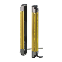
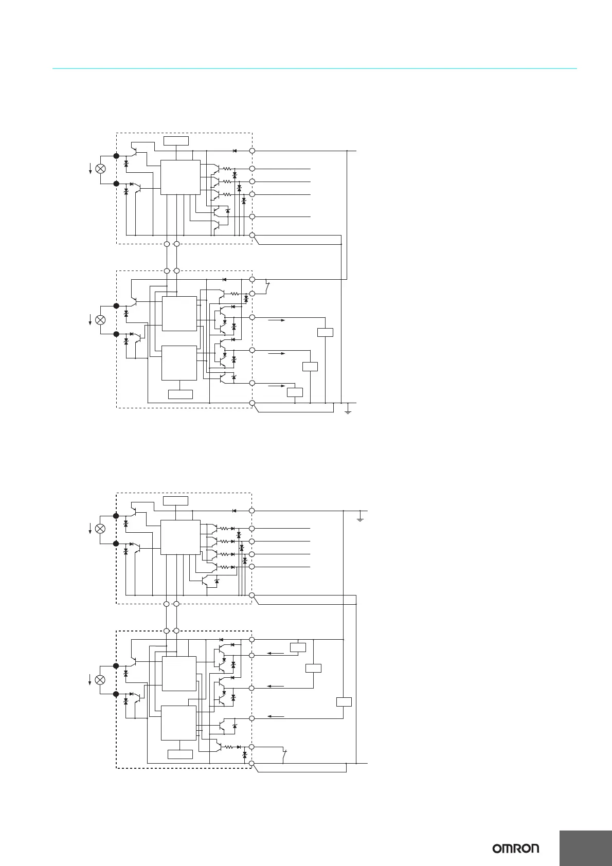
Input/Output Circuit Diagram
Entire Circuit Diagram
The numbers in circles indicate the connectors' pin numbers.
The black circles indicate connectors for series connection.
The words in brackets ([ ]) indicate the signal name for muting system.
*1. Open or muting input 1 for models with the "-TS" suffix.
*2. Open or muting input 2 for models with the "-TS" suffix.
The numbers in circles indicate the connectors' pin numbers.
The black circles indicate connectors for series connection.
The words in brackets ([ ]) indicate the signal name for muting system.
Shield
Shield
Emitter
Main Circuit
Indicator
Indicator
Receiver
Main Circuit 2
Receiver
Main Circuit 1
+24 VDC Brown
Brown
Black
Test input
White
Interlock selection input
[Muting input 1] *1
Red
Auxiliary output 2
[Muting input 2] *2
Reset input
Yellow
Blue
Blue
Brown
Blue
Brown
Auxiliary output 1
Yellow
Black
Safety output 1
Red
External device
monitoring input
White
Saf
ety output 2
Blue
Load
Load
0 V
Communication line (−)
Pink
Gray
Gray
Pink
Communication line (+)
Load
Exter
nal indicator output 1
External indicator output 2
2
8
1
2
3
1
4
7
8
5
5
6
6
3
4
7
[NPN Output]
0 V
2
1
8
2
3
1
4
7
8
5
5
6
6
3
4
7
Shield
Shield
Emitter
Main Circuit
Indicator
Indicator
Receiver
Main Circuit 2
Receiver
Main Circuit 1
+24 VDC
Brown
Brown
Black
Test input
White
Interlock selection input
[Muting input 1]
Red
Auxiliary output 2
[Muting input 2]
Reset input
Yellow
Blue
Blue
Brown
Blue
Brown
Auxiliary output 1
Yellow
Black
Safety output 1
Red
External device monitoring input
White
Safety output 2
Blue
Load
Load
Communication line (−)
Pink Gr
ay
Gra
y Pink
Commu
nication line (+)
Load
External indicator output 1
External indicator outpu
t 2
 Loading...


