F3SJ-A
17
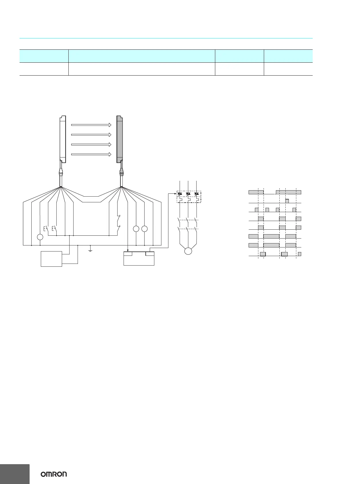
Connection Circuit Examples
Wiring for single F3SJ-A application
Note: The above PL is only the evaluation result of the example. The PL must be evaluated in an actual application by the customer after confirming
the usage conditions.
Application Overview
• The power supply to the motor M is turned OFF when the beam is blocked.
• The power supply to the motor M is kept OFF until the beams are unblocked and the reset switch S2 is pressed.
Highest achievable PL/
safety category
Model Stop category Reset
PLe/4 equivalent
Safety Light Curtain F3SJ-A@@@@P@@
Safety Relay G7SA
0 Manual
* Auxiliary output 1 gives inverted signal of safety output (default setting).
S1
S2
KM1
KM2
OUT
PLC
IN
KM3
KM2 KM1
Auxiliary output 2 (Red)
Interlock selection input (White)
Unblocked
Blocked
External test switch (S1)
Reset switch (S2)
Safety output
KM1,KM2 N.O. contact
KM1,KM2 N.C. contact
PLC input *
PLC output
- Using external device monitoring function
S1 : External test switch
(connect to 0 V if a switch is not required)
S2 : Interlock/lockout reset switch
KM, KM2 : Safety relay with force-guided contact (G7SA)
or magnetic contactor
K1 : Load, PLC (for monitor)
KM3 : Solid state contactor (G3J)
M : 3-phase motor
PLC : Programmable controller
(Used for monitoring -- not related to safety system)
K1
0 V
+24 VDC
Test input (Black)
Auxiliary output 1 (Yellow)
Safety output 1
(Black)
Power
supply
Receiver
Emitter
Shield
Reset input (Yellow)
Shield
External device
monitoring input (Red)
0 V (Blue)
0 V (Blue)
(Gray)
Communication line (+)
(Pink)
Communication
line (-)
+24 V (Brown)
+24 V (Brown)
Safety output 2
(White)
F39-JD@A-L F39-JD@A-D
M
KM2
KM1
 Loading...


