F3SJ-A
18
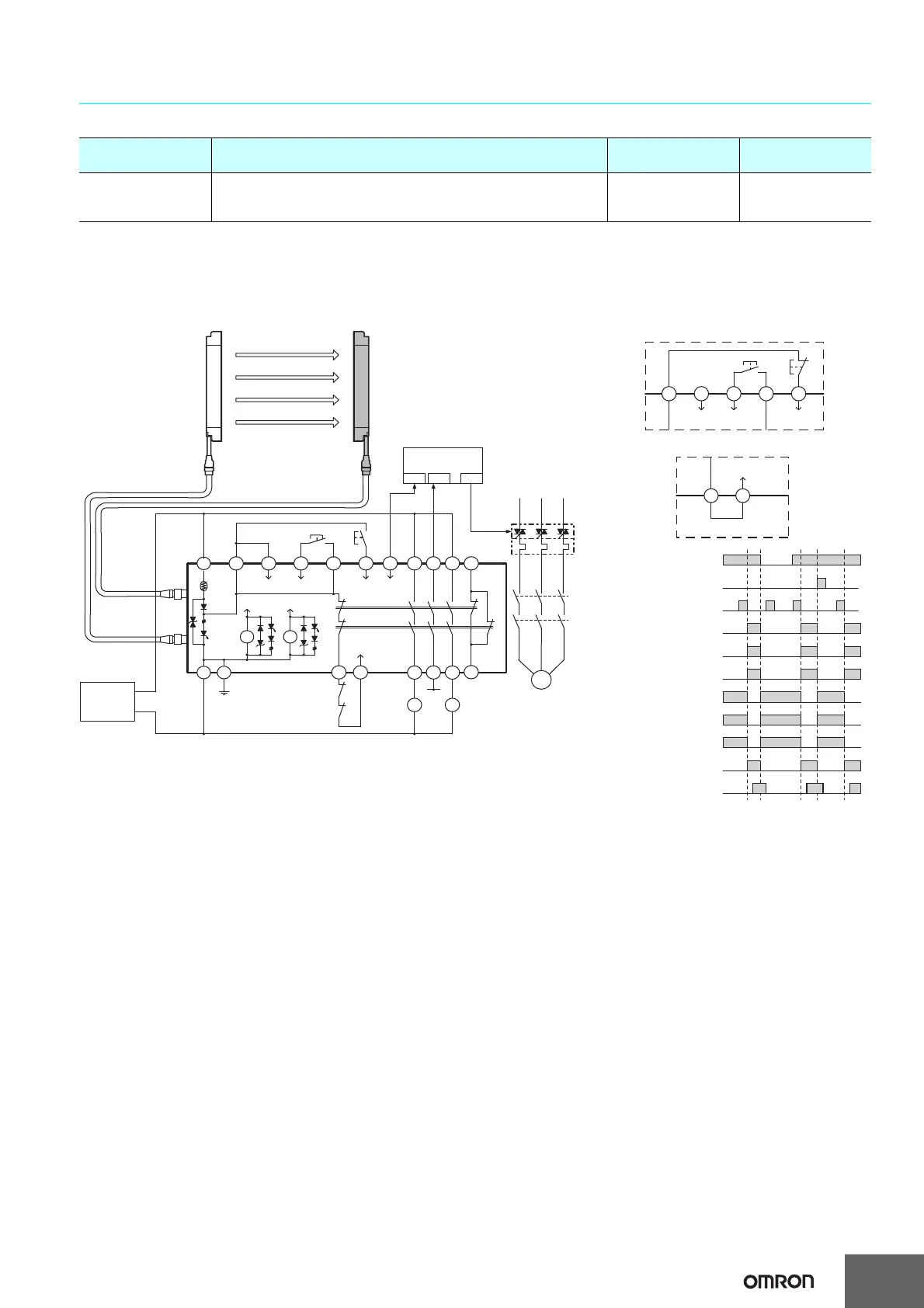
Wiring for connection with a controller F3SP-B1P
Note: The above PL is only the evaluation result of the example. The PL must be evaluated in an actual application by the customer after confirming
the usage conditions.
Application Overview
• The power supply to the motor M is turned OFF when the beam is blocked.
• The power supply to the motor M is kept OFF until the beams are unblocked and the reset switch S2 is pressed.
Note: It cannot be used as a muting system when F3SP-B1P is used.
Highest achievable PL/
safety category
Model Stop category Reset
PLe/4 equivalent
Safety Light Curtain F3SJ-A@@@@P@@
Control Unit F3SP-B1P
Safety Relay G7SA
0 Manual
[PNP Output]
Safety
output 1
Safety
output 2
K1
K2
F3SP-B1P
* Auxiliary output 1 gives inverted signal of safety output (default setting).
Wiring for auto reset mode
T32
T31
Wiring when the external device
monitoring function will not be used
External device
monitoring
Included short bar
+24V
KM3
PLC
IN1 IN2 OUT
S1
S2
Reset
Auxiliary
output 1
External device
monitoring
Test
Interlock
selection
Unblocked
Blocked
External test switch (S1)
Reset switch (S2)
Safety output
K1,K2 N.O. contact
KM1,KM2 N.O. contact
K1,K2 N.C. contact
KM1,KM2 N.C. contact
PLC input 1 *
PLC input 2
PLC output
Reset
Test
Interlock
selection
- Using external device monitoring function
S1 : External test switch
S2 : Interlock/lockout reset switch
KM1, KM2 : Safety relay with force-guided
contact (G7SA) or magnetic contactor
KM3 : Solid state contactor (G3J)
M : 3-phase motor
PLC : Programmable controller
(Used for monitoring -- not related to safety
system)
T31 T32
14 24 34 42
A2 PE
A1 H1 L1 J1 H1 X1 P1 13 23 33 41
KM1
KM2
KM1
KM2
K1 K2
Receiver Emitter
F39-JD@B-L F39-JD@B-D
0 V
+24 VDC
Power
supply
M
KM2
KM1
S1
S2
X1H1J1L1H1
 Loading...


