F3SJ-A
19
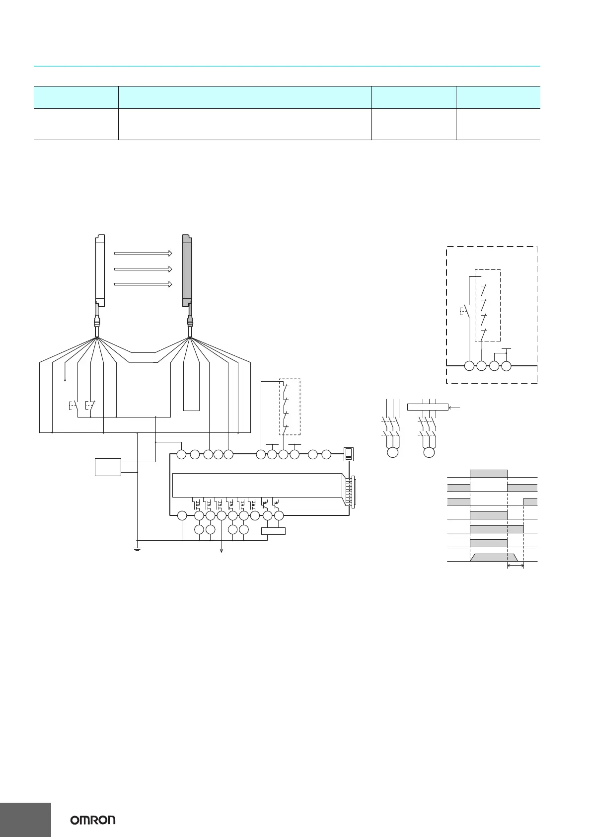
Wiring for connection with a controller G9SX-AD322-T15
Note: The above PL is only the evaluation result of the example. The PL must be evaluated in an actual application by the customer after confirming
the usage conditions.
Application Overview
• The power supply to the motor M1 is turned OFF immediately when the beam is blocked, and stop command is sent to the motor
controller for the motor M2.
• The power supply to the motor M2 is turned OFF after OFF-delay time.
• The power supply to the motor M1 and M2 is kept OFF until the beams are unblocked.
Highest achievable PL/
safety category
Model Stop category Reset
PLe/4 equivalent
Safety Light Curtain F3SJ-A@@@@P@@
Flexible Safety Unit G9SX-AD322-T15
Safety Relay G7SA
M1: 0
M2: 1
Auto
A1
A2
S14 S24
KM1 KM2
S34 S44
S54
KM3 KM4
L1 X1 X2
T11
KM1
KM2
KM3
KM4
+24 V
+24 V
T12
T21
T22
T31
T32 T33
Y1
T41 T42
PLC, etc.
Motor controller
Motor controller
(operation command)
Feedback loop
Open
G9SX-AD322-T15
Open Open Open
OFF
A
ND
S34
Control circuit
Safety output
KM1,KM2 N.C. contact
KM3,KM4 N.C. contact
KM1,KM2 N.O. contact
KM3,KM4 N.O. contact
Motor operation command
Motor rotation
OFF-delay time
Open
- F3SJ settings
- Auto reset mode
- Not using external device monitoring
- G9SX-AD322-T15 settings
- Auto reset mode
- Using feedback loop
S1 :External test switch (connect to 0 V if a switch is not required)
S2 :
Lockout reset switch (connect to 24 V if a switch is not required)
KM1 to KM4 : Safety relay with force-guided contact (G7SA)
or magnetic contactor
M1, M2 : 3-phase motor
PLC : Programmable controller
(Used for monitoring -- not related to safety system)
+24 V
T32 T33
Y1
KM3
KM4
T31
KM1
KM2
Wiring for manual reset mode
Feedback loop
S3: Reset switch
Receiver Emitter
F39-JD@A-L F39-JD@A-D
Auxiliary output 2 (Red)
Interlock selection
input (White)
0 V
+24 VDC
Test input (Black)
Auxiliary output 1
(Yellow)
Safety output 1 (Black)
Power
supply
Shield
Reset input (Yellow)
Shield
External device
monitoring input (Red)
0 V (Blue)
0 V (Blue)
(Gray)
Communication
line (+)
(Pink)
Communication
line (−)
+24 V (Brown)
+24 V (Brown)
Safety output 2 (White)
M1 M2
KM1
KM2
KM3
KM4
S1
S2
S3
 Loading...


