the usage conditions.
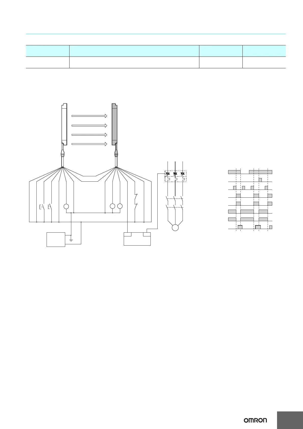
External test switch (S1)
Reset switch (S2)
KM1,KM2 N.O. contact
KM1,KM2 N.C.contact
PLC input *
PLC output
Safety output
Unbloc
ked
Blocked
* Auxiliary output 1 gives inverted signal of safety output (default setting).
OUT
PLC
IN
KM3
KM1
KM2
KM1
K1
KM2
S1 : External test switch
(connect to 24 V if a switch is not required)
S2 :
Interlock/lockout reset switch
KM1, KM2 : Safety relay with forcibly-guided contacts (G7SA)
or magnetic contactor
K1 : Load, PLC (for monitor)
KM3 : Solid state contactor (G3J)
M : 3-phase motor
PLC : Programmable controller
(Used for monitoring -- not related to safety system)
- Using external device monitoring function
Receiver Emitter
F39-JD@A-L F39-JD@A-D
Auxiliary
output 2 (Red)
Interlock selection input (White)
Test input (Black)
Auxiliary output 1 (Yellow)
Safety output 1 (Black)
Shield
Reset input (Yellow)
Shield
External device
monitoring input (Red)
0 V (Blue)
0 V (Blue)
Communication
line (+) (Gray)
Communication
line (−) (Pink)
+24 V (Brown)
+24 V (Brown)
Safety output 2 (White)
0 V
+24 VDC
Power
supply
S1
S2
M
KM1
KM2
 Loading...


