F3SJ-E/F3SJ-B/F3SJ-A
42
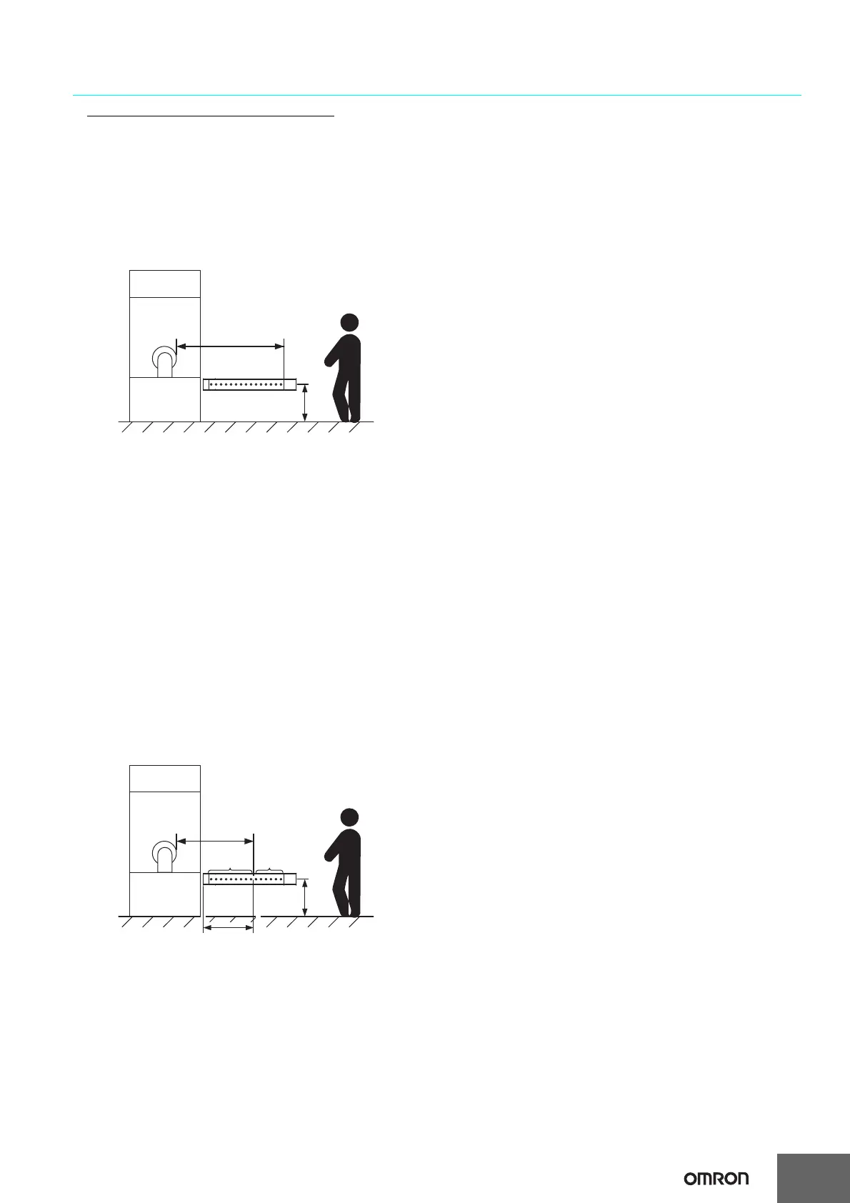
Detection Zone Parallel to Direction of Approach
Use K = 1,600 mm/s and C = (1200 - 0.4 x H) in formula (1) for
calculation. Note that C must not be less than 850 mm.
S = 1,600 mm/s x (Tm + Ts) + 1200 - 0.4 x H
• S = Safety distance (mm)
• Tm = Machine's response time (s)
• Ts = Response time of F3SJ from ON to OFF (s)
• H = Installation height (mm)
Note that H must satisfy:
1000
≥ H ≥ 15 (d - 50 mm) ≥ 0 mm
Also, you must include a hazardous condition under which a
person may go through under a detection zone if H exceeds 300
mm (200 mm for other purpose than industrial use) into risk
assessment.
[Calculation example]
When Tm = 0.05 s, Ts = 0.01 s, and d = 14 mm:
S = 1,600 mm/s x (0.05 s + 0.01 s) + 1200 - 0.4 x 500 mm
= 1096 mm
When a warning zone is configured as in the figure, you must
calculate L, a distance from an end of casing to a detection zone,
using a formula below:
L = (Total number of F3SJ beams - number of warning zone beams
- 1) x P + 10
•
P: Beam Gap (mm)
•F3SJ-A@@@@P14/N14 . . . 9 mm
•F3SJ-A@@@@P20/N20 . . . 15 mm
•F3SJ-A@@@@P25/N25 . . . 20 mm
•F3SJ-A@@@@P30/N30 . . . 25 mm
•F3SJ-A@@@@P55/N55 . . . 50 mm
Refer to the F3SJ User's Manual for details. For manual number,
check the "Related Manuals" at the end of the catalog.
How to calculate the safety distance specified by
American standard ANSI B11.19
(Ref.)
If a person approaches the detection zone of the F3SJ
orthogonally, calculate the safety distance as shown below.
S = K x (Ts + Tc + Tr + Tbm) + Dpf
• S: Safety distance
• K: Approach speed to the detection zone
(the value recommended by OSHA standard is 1,600 mm/s)
Approach speed K is not specified in the ANSI B.11.19 standard.
To determine the value of K to apply, consider all factors, including
the operator's physical ability.
• Ts = Machine's stop time (s)
• Ts = Response time of the F3SJ from ON to OFF (s)
• Tc = Machine control circuit's maximum response time required
to activate its brake (s)
• Tbm = Additional time (s)
If a machine has a brake monitor, "T
bm = Brake monitor setting
time - (Ts + Tc)"
. If it has no brake monitor, w
e recommend using
20%
or more of (Ts + Tc) as additional time.
• Dpf = Additional distance
According to ANSI's formula, Dpf is calculated as shown below:
Dpf = 3.4 x (d - 7.0): Where d is the detection capability of the F3SJ
(unit: mm)
[Calculation example]
When K = 1,600 mm/s, Ts + Tc = 0.06 s, brake monitor setting time
= 0.1 s, Tr = 0.01 s, and d = 14 mm:
Tbm = 0.1 - 0.06 = 0.04 s
Dpf = 3.4 x (14 - 7.0) = 23.8 mm
S = 1,600 mm/s x (0.06 s + 0.01 s + 0.04 s) + 23.8 mm = 199.8 mm
H
Safety distance (S)
Hazard
H
Safety
distance (S)
Hazard
Distance L from casing end
to detection zone
Detection
zone
Warning
zone

 Loading...


