Setting Method
NPN Open-collector Output Models
DIP Switch 1 Mode Switching
Emitters
*1. DIP Switch 1 Picking Display Mode Setting
*2. The flashing speed can be changed in picking display mode (all flashing,
elevator-like lighting, or accordion-like lighting) or in external picking display
mode. The flashing speed varies with each display mode.
*3. This setting is supported for F3W-D052@P-L Emitters only.
*4. Mutual Interference Prevention Function:
The frequency selector is used to switch the emitting frequency between A
and B. Making the emitting frequencies of two Sensors different helps
prevent malfunction caused by mutual interference.
Receivers
Models with Direct UNI-WIRE Connection
Setting Addresses
(1) Set the picking instruction input address using DIP switch 2
on the Emitter and Receiver.
(2) Set the control output addresses using DIP switch 3 on the
Receiver.
• The total number of switch addresses set to ON
determines the set address (e.g., address 22 in
the diagram at right).
• Make sure that the addresses of the picking
instruction inputs of the Emitter and the
Receiver that are used as a set are the same.
Transmission Status
The transmission indicator indicates the status of
bus transmission as follows:
Flashing: Normal operation
ON or OFF: Transmission error
Only one picking indicator flashing also indicates a transmission error.
Weight
The weight of the F3W-D052U in the UNI-WIRE SYSTEM is the
weight of one terminal consisting of the Emitter and Receiver pair.
IDs
IDs are set separately for the Emitter and the Receiver.
Emitter: The picking instruction input address setting is the ID
address.
Receiver: The control output address setting is the ID address.
Note: The ID is an identification number for broken wire position detection.
Power Supply
If a power voltage drop occurs in a remote section, consider using a
local (separate) power supply.
DIP
switch 1
Function
OFF (left)
()
ON (right)
()
1
Flash Pattern
(picking display mode setting)
See table below. *1
2
3
Flash Time *2
(picking indicator flashing speed
setting)
Slow Fast
4
External Flash Pattern
(external picking display mode
setting) *3
Lit Flashing
5 Not used. --- ---
6 Frequency Setting *4
A
(frequency A)
B
(frequency B)
DIP
switch 1
SW
1-1
SW
1-2
Display mode
OFF OFF
All lighting
(All six indicators light.)
ON OFF
All flashing
(All six indictors flash simultaneously.)
OFF ON
Elevator-like lighting
(Two adjacent indicators simultaneously
light so that lighting moves up and down.)
ON ON
Accordion-like lighting
(Some or all indicators simultaneously light
so that lighting moves like an accordion.)
1
6
5
4
3
2
1
6
5
4
3
2
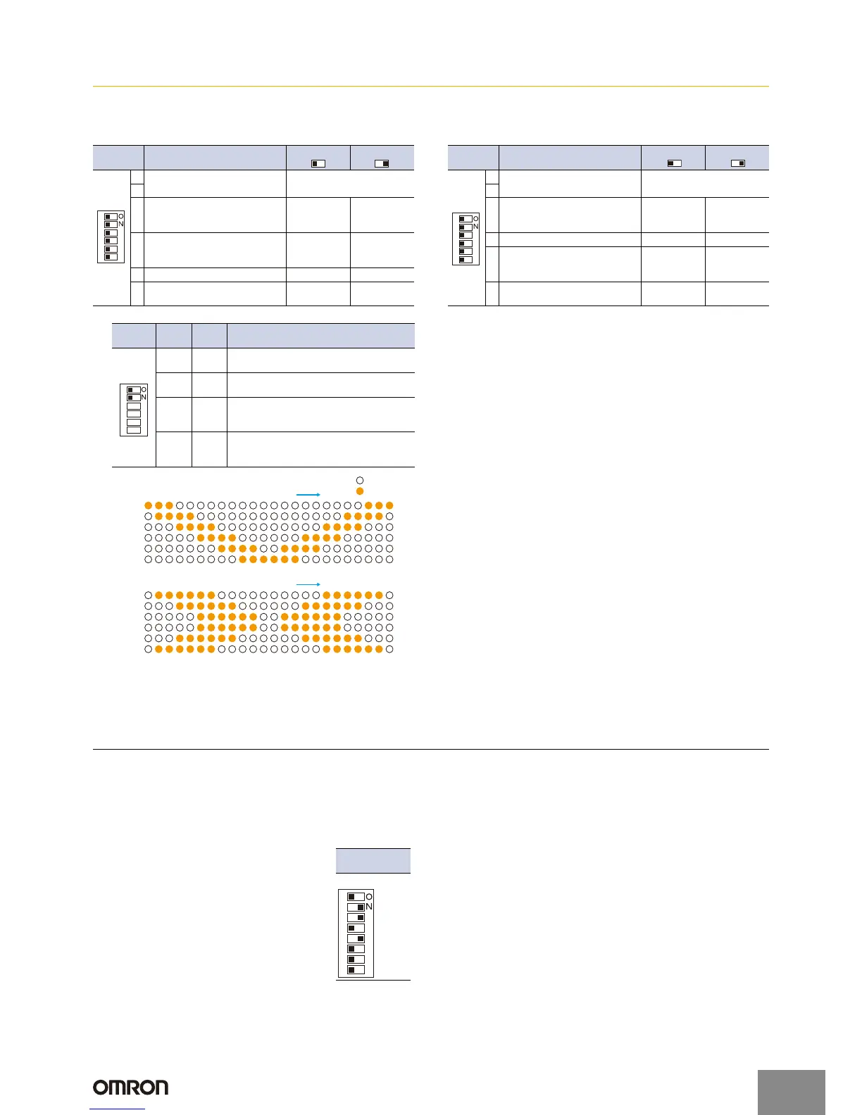
LED1
• Elevator-like Lighting Mode
LED2
LED3
LED4
LED5
LED6
Changes in Indicators
Not lit
Lit
LED1
• Accordion-like Lighting Mode
LED2
LED3
LED4
LED5
LED6
Changes in Indicators
DIP
switch 1
Function
OFF (left)
()
ON (right)
()
1
Flash Pattern
(picking display mode setting)
See table below. *1
2
3
Flash Time *2
(picking indicator flashing speed
setting)
Slow Fast
4 Operation mode setting Dark-ON Light-ON
5
Sensing distance (sensitivity)
setting
LONG
mode
(1 to 3 m)
SHORT
mode
(0.05 to 1 m)
6
Frequency Setting
(F3W-D052U@ only) *4
A
(frequency A)
B
(frequency B)
1
6
5
4
3
2
DIP switches
2 and 3
11
Number of
addresses
−
8
7
6
5
4
3
2
128
−
64
−
32
−
16
−
8
−
4
−
2
−
http://www.ia.omron.com/
7
(c)Copyright OMRON Corporation 2008 All Rights Reserved.