Do you have a question about the Omron D6T Series and is the answer not in the manual?
Describes the purpose and scope of the user manual for D6T-series MEMS Thermal Sensors.
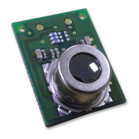
Explains the components and arrangement of the D6T MEMS Thermal Sensor module and its exterior.
Details the physical dimensions of the D6T MEMS Thermal Sensor circuit board.
Shows a diagram illustrating the internal configuration and components of the sensor module.
Compares the operational characteristics of MEMS Thermal Sensors with pyroelectric sensors.
Illustrates the Field of View and sensitivity characteristics of the thermal sensors.
Details the steps and procedures for using the MEMS Thermal Sensors.
Identifies the product's connector pin assignments and lists material specifications.
Illustrates a direct connection method for a 5V microcontroller.
Shows a connection setup for a 3V MCU with a 5V fault-tolerant I2C port.
Demonstrates how to use an I2C level converter for voltage mismatch.
Explains how to use a GPIO terminal for I2C communication processing.
Details how to connect multiple D6T sensors using an I2C bus-switching IC.
Lists I2C communication parameters like slave address, data length, and clock speed.
Shows a timing diagram for I2C data transmission for the 16-channel model.
Illustrates the I2C data flow for the 8-channel D6T-8L-09 model.
Displays I2C data transmission timing for 1-channel and 1024-channel models.
Illustrates pixel arrangement for temperature data across different channel models.
Displays the signal timing for I2C communication between MCU and sensor.
Defines the symbols used in the I2C signal timing diagrams.
Explains I2C start/stop conditions and shows write operation timing.
Details the D6T-32L-01 register map and explains the IIR filter functionality.
Provides sample data and C code for 16 and 1024-channel models.
Presents code modifications specific to the 1-channel D6T models.
Provides sample data and C code for 16 and 1024-channel models.
Presents code modifications specific to the 1-channel D6T models.
Implements a CRC-8 calculation function for PEC checking.
Details the PEC check process for Stop-Start I2C reads.
Outlines the routine for detecting and handling I2C clock stretch by the master.
Illustrates the signal flow and timing for the I2C wait detection process.
Explains the conditions and behavior of communication timeouts in the sensor.
Advises on selecting suitable cover materials for optimal sensor performance.
Shows how HDPE thickness affects transparency and sensor detection.
Displays diagrams showing the mountable areas for different D6T models.
Offers a reference illustration for securing the sensor.
Addresses questions about increasing the field of view and its limitations.
Explains that infrared signals from remote controllers do not cause incorrect operation.
Clarifies that the sensor provides temperature data; distinction relies on software.
Discusses the effective detection distance when used as a human sensor.
Explains that power reduction requires shutting off power to the sensor.
States that 3V drive and slave address are not configurable for D6T sensors.
Describes the time required for the sensor to reach stable operation after power-up.
Defines a thermopile as a device cascaded to a thermocouple to increase voltage.
Defines NETD as a measure of noise converted into temperature, representing resolution.
Defines FOV as the viewing angle index, often based on 50% sensitivity.
The Omron D6T MEMS Thermal Sensor is a sophisticated device designed for measuring the surface temperature of objects. It integrates a silicon lens, a thermopile sensor, and specialized analog and logic circuits on a small circuit board to convert thermal energy into a digital temperature value. This compact design, available in various sizes (e.g., 14 mm x 18 mm or 11.6 mm x 12 mm), requires only a single connector for system integration, simplifying its use in diverse applications.
The core principle of operation involves the silicon lens focusing radiant heat (far-infrared rays) emitted from objects onto the thermopile sensor. The thermopile sensor then generates an electromotive force proportional to the focused radiant energy. This electromotive force, along with data from an internal thermal sensor, is used by the device to calculate the object's temperature through an interpolation process, comparing measured values with an internally stored lookup table. The resulting temperature value is output via the I2C bus, ready to be read by a host system.
The D6T series offers different channel configurations to suit various needs. For instance, the D6T-44L-06 model features 16 channels in a 4x4 arrangement, while the D6T-8L-09 has an 8-channel array. The D6T-1A-01 and D6T-1A-02 models are equipped with a single-channel sensor chip. The module's design optimizes the placement of the downstream processing circuit adjacent to the sensor chip, ensuring low-noise temperature measurements.
A key advantage of the MEMS Thermal Sensor over conventional pyroelectric sensors is its ability to continuously generate a measurement signal, even when there is no movement. Pyroelectric sensors detect movement based on changes in infrared rays, meaning their signal is lost during periods of stillness. This makes the D6T series particularly suitable for applications requiring constant presence detection, such as human sensing, without the limitations of motion-dependent sensors.
The silicon lens is optically designed to provide specific sensitivity characteristics. The sensors maintain a consistent field of view (FOV) at a maximum sensitivity of 50% compared to general sensors. It's important to note that the sensitive areas of the elements are wider than the FOV-specification width. If the measured object is smaller than the sensitive area of an element, the background temperature of other objects can influence the reading. The sensors use a reference heat source (a blackbody furnace) for temperature value correction, but factors like object emissivity, surface shape, and the occupancy ratio of objects within sensitive areas can still affect temperature values.
The measurable area (FOV) expands as the distance to the measured object increases. Consequently, the occupancy ratio of objects (e.g., people) within the FOV decreases with distance. This means that at greater distances, the temperature values become more representative of the background temperature rather than the intended object's temperature. For accurate temperature measurement of intended objects, the object must be sufficiently larger than the FOV area. When used as a human sensor, the D6T is primarily limited to close-distance applications for simple temperature value determination. To enhance detection distance and accuracy, software processing that incorporates temporal changes, heat source positions, and human behavior information is recommended.
The D6T MEMS Thermal Sensors are designed for straightforward integration into various systems. They utilize a 4-pin connector (SM04B-GHS-TB (JST) with SSHL-002T-P0.2 (JST) contacts and GHR-04V-S (JST) housing) for power supply and I2C communication. The VCC power supply pin operates at 5 V ±10%.
Several electrical connection scenarios are supported:
The I2C communication specifications include a 7-bit slave address (0001_010b), 8-bit data length (MSB-first), and a maximum clock speed of 100 kHz (1000 kHz for D6T-32L only in Fast-Mode Plus). Clock stretch support is available for all models except D6T-1A-01, D6T-1A-02, and D6T-8L-09.
The sensor's output data includes PTAT (Proportional To Absolute Temperature) and Pn (pixel temperature) values, which are signed 16-bit integers representing temperature values in °C multiplied by a factor of 10. For example, 25.0°C is represented as 250 (0x00FA), and -25.0°C as -250 (0xFF06). The output data also includes a Packet Error Check (PEC) code, which is a CRC-8 error check data appended to the end of communication output. This PEC value allows users to detect communication errors and enhance data reliability.
For D6T-8L-09 models, an initial processing step is required at least 20 msec after power-on, which should only be performed once at power startup. Similarly, for the D6T-32L-01A, register settings can be changed, and this processing should also be performed at least 20 msec after power-on, only at power startup. The D6T-32L-01A allows setting an IIR filter coefficient (0 to 15) to adjust temperature averaging.
The D6T-1A-01/02 and D6T-8L-09 models do not feature clock stretch. For models that do, the slave (sensor) can generate a signal to the master (MCU) to request a wait period before sending a request, based on the temperature data state. The master MCU must support this wait processing. If the MCU's I2C module lacks automatic clock stretch support, a wait detection routine must be added to the SCL output portion of the program. Alternatively, a fixed 160 µsec wait time can be added at every Ack timing.
Communication timeouts are implemented to prevent indefinite waiting. If low input is continuously received on the SDA or SCL terminal for 1 second (D6T-44L-06) or 70 msec (D6T-1A-01/02/8L-09), the sensor determines a timeout has occurred and stops communication. During a Write access operation, a NACK is returned. For Read access operations, the read value is set to FFFFh. Using PEC for data checking is recommended to identify erroneous read values.
The D6T MEMS Thermal Sensor is designed for robust and reliable operation, but certain considerations are important for its long-term performance and integration:
The D6T series is designed for reliability and ease of use, providing a robust solution for various thermal sensing applications with careful attention to integration and operational guidelines.
| Model Series | D6T |
|---|---|
| Detection Method | Non-contact |
| Interface | I2C |
| Output Type | Digital |
| Type | Thermal Sensor |
| Field of View | Varies by model |
| Number of Pixels | Varies by model |
| Operating Temperature | Varies by model |
| Storage Temperature | Varies by model |
| Response Time | Varies by model |
| Dimensions | Varies by model |
| Humidity Range | 85% (non-condensing) |