13 D6T MEMS Thermal Sensors User’s Manual (A284)
Fig. 18. Signal Terminal Flow (D6T-32L-01)
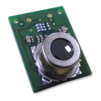
Fig. 19. Start/Stop Conditions
On the D6T-32L-01A, the settings in Table 4 can be changed. Before performing the processing in
Fig. 19, perform the processing below at least 20 msec after supplying power to the product. Only
perform this processing at power startup.
Fig. 20. Write (D6T-32L-01)
Table 4. Register map (D6T-32L-01)
:
:
:
:
b3-b0(WR) : Average(0 to 10)
:
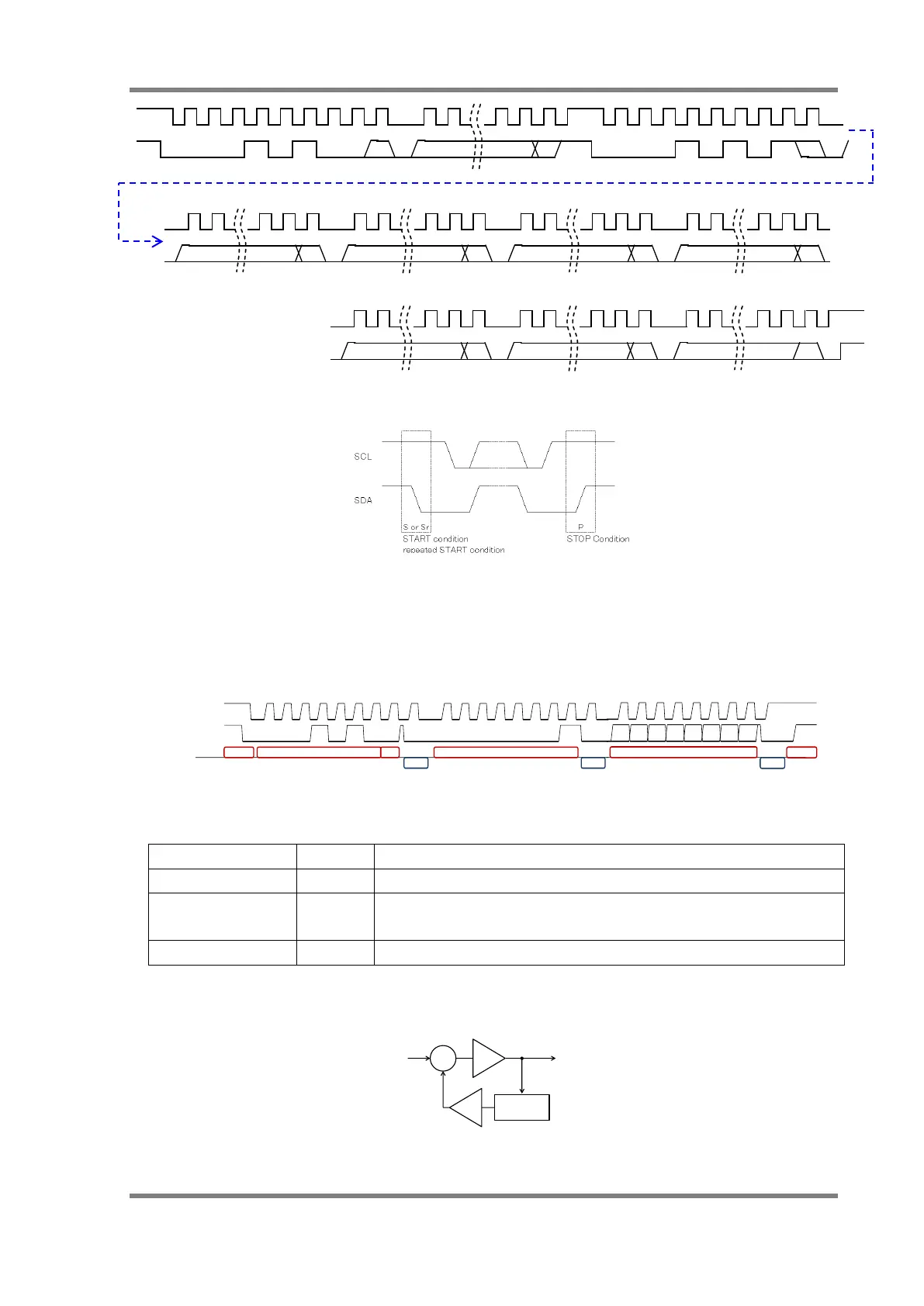
The IIR filter coefficient can be set to 0 (through) or a value from 1 to 15.
Taking C to be 4 times the set value, the equation is Y= ((C-1) × Yold + X)/C.
Fig. 21. IIR filter
slave address[6:0] (0x0A)
slave address[6:0] (0x0A)
Slave Address W
Ack
Start Registor Address
Ack
Master
Slave
 Loading...


