D6T MEMS Thermal Sensors User’s Manual (A284) 2
1 Overview
This user manual describes the usage procedures, precautions, and other information regarding
D6T-series MEMS Thermal Sensors. This document also serves as a supplement to the product
catalog. Reference this document together with the product catalog when using this device.
2 Structure (Part Configuration)
The D6T series of MEMS Thermal Sensors consists of a
small circuit board onto which a silicon lens, thermopile
sensor, specialized analog circuit, and logic circuit for
conversion to a digital temperature value are arranged.
This product only requires one connector to connect
these modules.
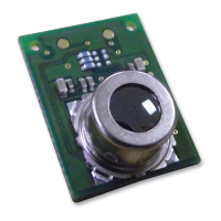
3 External Dimensions
This product features a circuit board size of 14 mm x 18 mm. An even more compact size of
11.6 mm x 12 mm is also available. Refer to the product catalog for more information on
mounting areas and positioning of the circuit board. Refer to Chapter 6 for more information on
compatible connectors.
4 Principles of Operation
The following list describes an overview of the measuring
operation of the MEMS Thermal Sensors.
· The silicon lens focuses radiant heat (far-infrared
rays) emitted from objects onto the thermopile sensor
in the module. (*1)
· The thermopile sensor generates electromotive force
in accordance with the radiant energy (far-infrared
rays) focused on it.
· The values of this electromotive force and the internal
thermal sensor are measured. Then, the device
calculates the measured value (temperature of the
object) via an interpolation calculation that compares
the measured values with an internally stored lookup
table. (*2)
· The measured value is output via the I2C bus, and read
using a host system.
(*1) The D6T-1A-01/02 models use a silicon filter.
(*2) D6T-1A-01/D6T-1A-02/D6T-8L-09 use a temperature conversion circuit in the ASIC
to calculate measured values (temperatures of objects).
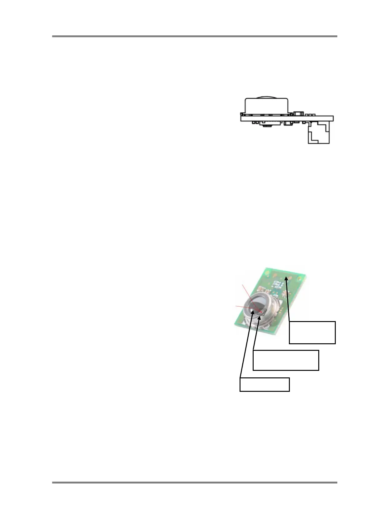
(Interior side)
Thermopile sensor
Silicon lens
(Back side)
I2C connector
Fig. 1. Exterior of Module (Reference)
Fig. 2. Module Configuration