5 D6T MEMS Thermal Sensors User’s Manual (A284)
6 Usage Procedure
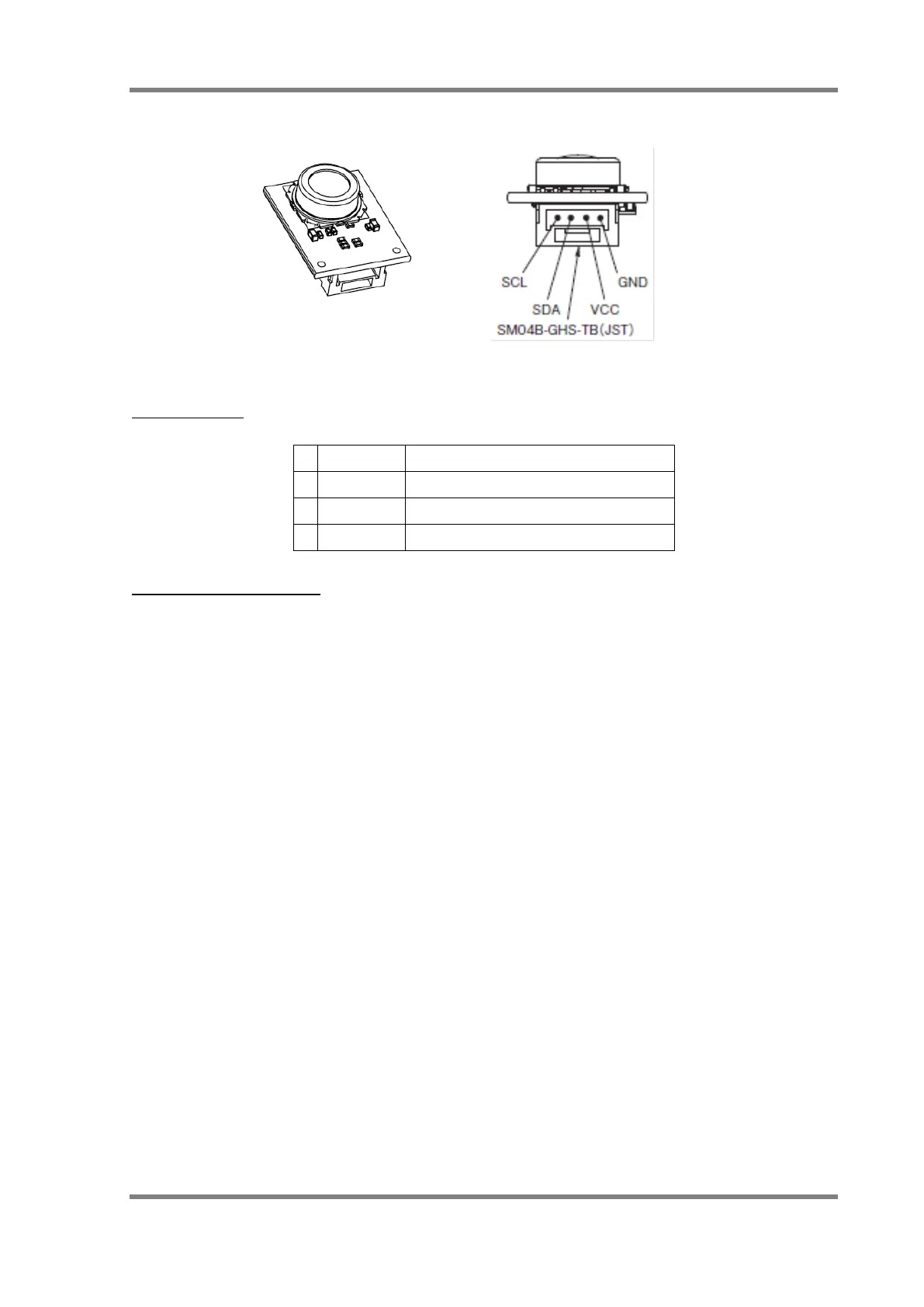
6.1 Connectors
Fig. 6. Product Exterior (Reference)
Connector Pins
Table 1. Connector Pin Table
VCC power supply pin (5 V ±10%)
Connector Parts Materials
Connector part model: SM04B-GHS-TB (JST)
Contact: SSHL-002T-P0.2 (JST)
Housing: GHR-04V-S (JST)
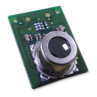
The lens height and circuit board size varies by model. Refer to the product catalog for more
information on dimensions. Use a 4-pin connector as described above to connect this module to
systems.
 Loading...


