New H3Y
New H3Y
131
Installation
Connection
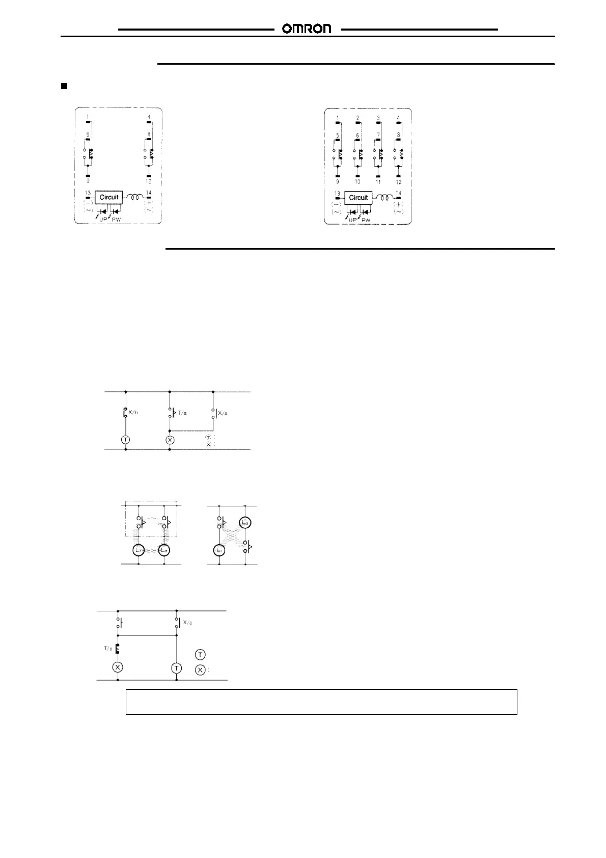
H3Y-2, H3Y-2-0 H3Y-4, H3Y-4-0
Connect the DC power supply to
terminals 13 and 14 according
to the polarity marks.
Connect the DC power supply to
terminals 13 and 14 according to
the polarity marks.
Precautions
When selecting a control output, use the H3Y-2 for switching ON
and OFF the power and the H3Y-4 for switching ON and OFF the
minute load.
Theoperatingvoltage willincrease whenusing the H3Yinanyplace
where the ambient temperature is more than 50
"
C. Supply 90% to
110% of the rated voltages (at 12 VDC: 95% to110%) whenoperat-
ing at 50
"
C or higher.
Do not leave the H3Y in time-up condition for a long period of time
(for example, more than one month in any place where the ambient
temperature is high), otherwise the internal parts (aluminum elec-
trolytic capacitor) may become damaged. Therefore, the use of the
H3Y with a relay as shown in the following circuit diagram is recom-
mended to extend the service life of the H3Y.
MY Relay
H3Y
Donot connect theH3Y asshown inthefollowingcircuit diagram on
the right hand side, otherwise the H3Y’s internal contacts different
from each other in polarity may become short-circuited.
Correct Incorrect
Use the following safety circuit when building a self-holding or self-
resetting circuit with the H3Y and an auxiliary relay, such as an MY
Relay, in combination.
:H3Y
Auxiliary relay:
MY Relay
Do not use the H3Y in places where there is excessive dust, corro-
sive gas, or direct sunlight.
Do not mount more than one H3Y closely together, otherwise the
internal parts may become damaged. Make sure that there is a
space of5 mm ormore betweenany H3YModels next to eachother
to allow heat radiation.
The internal parts may become damaged if a supply voltage other
thantheratedonesis imposedontheH3Y.Whenmorethan100Vis
applied to 12- or 24-VDC models, the internal element (varistor)
may break.
Precautions for VDE Conformance
The H3Y as a built-in timer conforms to VDE 0435/P2021 provided
that the following conditions are satisfied.
Handling
Before dismounting the H3Y from the socket, make sure that no
voltage is imposed on any terminal of the H3Y.
Wiring
The power supply for the H3Y must be protected with equipment
such as a breaker approved by VDE.
Only a load with basic isolation can be connected to the output con-
tact. The H3Y is a model with basic isolation. Therefore, the H3Y
and the load will ensure reinforced isolation, thus meeting VDE
standards.
Insulation requirement: Overvoltage category II,
pollution degree 2
(with a clearance of 1.5 mm and a creep-
age distance of 2.5 mm at 240 VAC)
Output terminals next to each other on the H3Y-4 or H3Y-4-0 must
have the same polarity.
ALL DIMENSIONS SHOWN ARE IN MILLIMETERS.
To convert millimeters into inches, multiply by 0.03937. To convert grams into ounces, multiply by 0.03527.
Cat. No. L24-E1-9