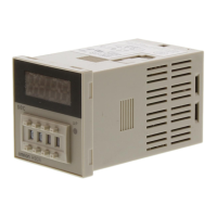
H3FA
H3FA
139
Operation
Timing Chart
H3FA-A/H3FA-B/H3FA-SA/H3FA-SB
Standard Operation (ON-delay Operation)
Integration Operation
OFF-delay Operation by External Signal
(See note)
(See note)
(See note)
H3FA-AU/H3FA-BU/H3FA-SAU/H3FA-SBU
One-shot Output Operation
OFF-delay Operation by External Signal
(See note)
(See note)
Note: When using the 12/24 VDC operated
timer with a 12 VDC power supply,
short-circuit terminals 13 and 15.
Note: 1. Control output is provided when the set time
(T
1
+T
2
or T
3
+T
4
) is up.
2. When usingthe12/24VDCoperatedtimerwith
a 12 VDC power supply, short-circuit terminals
13 and 15.
Note: When using the 12/24 VDC operated
timer with a 12 VDC power supply,
short-circuit terminals 13 and 15.
Note: 1. When using the 12 VDC operated timer suffixed
-S
j
U, short-circuit terminals 13 and 15.
2. T denotes set time.
t
1
,t
2
,t
3
,t
4
,<T
Note: 1. When using the 12 VDC operated timer suffixed
-S
j
U, short-circuit terminals 13 and 15.
2. T denotes set time.
t
1
,t
2
,t
3
,t
4
,<T

 Loading...