H3CR-A
H3CR-A
19
Engineering Data
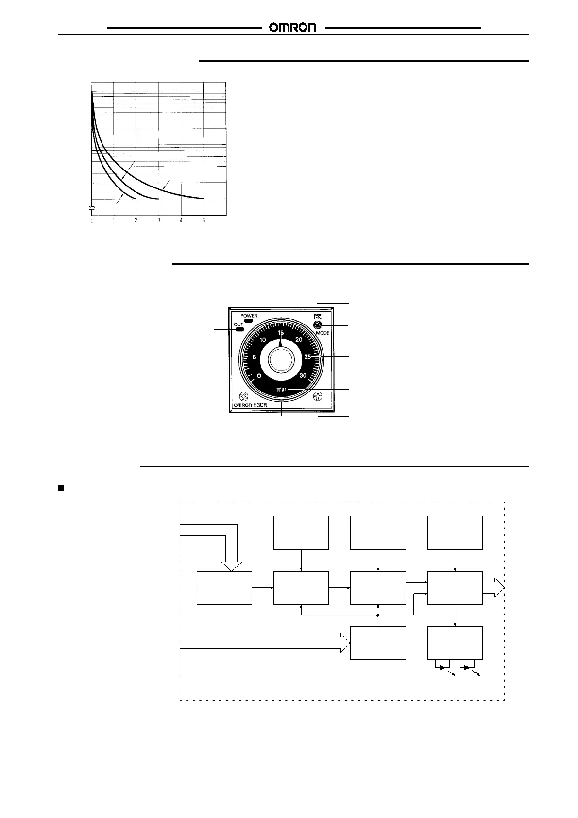
Reference: A maximum current of 0.15 A can be switched at 125 VDC (cos
%
=1)
and a maximum current of 0.1 A can be switched if L/R is 7 ms. In
both cases, a life of 100,000 operations can be expected.
The minimum applicable load is 10 mA at 5 VDC (failure level: P).
Load current (A)
30 VDC L/R = 7 ms
250VAC/30VDC
(cos
%
=1)
250 VAC (cos
%
=0.4)
Switching operations (x 10 )
3
10,000
5,000
1,000
500
100
Nomenclature
Power indicator (green) (Flashes when Timer
operates; lit when Timer stops operating)
Operating mode display window
Operating mode selector (select
a mode from A, B, B2, C, D, and
E (H3CR-A and -AS), A and E
(H3CR-A8, -A8S, -A8EL, -A8E)
Scale range display windows
Time unit display window
Time unit selector (select one
from sec, min, hrs, and 10h)
Time setting
knob (set time)
Output indicator (orange)
Time range selector
(select one from
1,2,3,12, and 30)
Operation
Block Diagrams
H3CR-A/AS
AC (DC) input
Power supply
circuit
Zero setting
detection
circuit
Oscillation
circuit
Time range/
unit selectors
Counting
circuit
Operating
mode selector
Output circuit
Reset input, start input, and gate input
Input circuit
Indicator
circuit
Power-ON
indicator
Output-ON
indicator