H5S
H5S
242
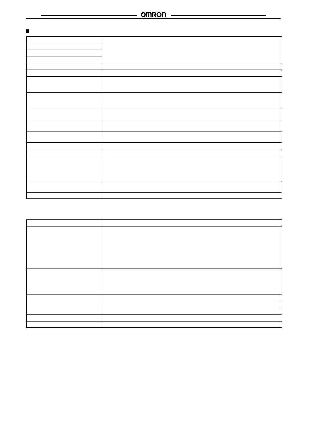
Characteristics
Accuracy of operating time
!
0.01%
!
0.05 s max. (see note)
Setting error
Influence of voltage
Influence of temperature
Cyclic error Monthly difference
!
15 s (at 25
"
C) (
!
4 s/week,
!
1 min/4 months)
Memory protection 5 years min. (at 25
"
C)
Insulation resistance 100 M
$
min. (between current-carrying terminals and non-current-carrying metal parts,
between operation circuit and contact control output circuit, and between non-continuous
contacts)
Dielectric strength 2,000 VAC, 50/60 Hz for 1 min (between current-carrying terminals and non-current-carrying
metal parts and between operation circuit and contact control circuit)
1,000 VAC, 50/60 Hz for 1 min (between non-continuous contacts)
Noise immunity 1,500 V (100 ns wide, for 1
&
s,1nsrisetime,
!
polarity, and 0
"
to 360
"
phase. Square noise
generated by noise simulator)
Vibration resistance Destruction: 10 to 55 Hz with 0.75-mm double amplitude
Malfunction: 10 to 55 Hz with 0.5-mm double amplitude
Shock resistance Destruction: 294 m/s
2
(30G)
Malfunction: 98 m/s
2
(10G)
Ambient temperature Operating: --10
"
Cto55
"
C
Ambient humidity Operating: 35% to 85%
Life expectancy 50,000 operations min. (15 A at 250 VAC, resistive load)
50,000 operations min. (1 HP at 250 VAC, motor load)
50,000 operations min. (10 A at 250 VAC, inductive load (cos
%
=0.7))
50,000 operations min. (100 W at 100 VAC, lamp load)
10,000 operations min. (300 W at 100 VAC, lamp load)
Approved standards UL (File No. E52800), CSA (File No. LR22310, 10 A at 250 VAC (general use), 15 A at
125 VAC (resistive load))
Weight Approx. 200 g
Note: The total error including therepeataccuracy, settingerror,variation due tovoltage change,and variationdue to temperature change is
!
0.01%
!
0.05 s max.,
!
0.01% indicates an error in the time interval of a set time.
Operation
Operation method Digital quartz
Operation 1. Weekly operation (multiple-day operation possible)
2. Cyclic operation
3. Pulse-output operation (Pulse width can be set in units of 1 s from 1 to 59 s and in units of
1minfrom1to60min.)
4. Day override operation (Operation for one day can be also executed on any other day.)
5. Forced ON/OFF Operation
6. Manual or automatic operation selectable on recovery from power failure.
Display Digital indication by LCD (character height: 10 mm)
1. Day, hrs (a.m., p.m.), minutes (0:00 to 11:59 a.m., 0:00 to 11:59 p.m.)
2. Digital display of operation schedule during operation
3. Timing chart display of operation schedule during operation
Number of circuits 2 independent circuits
Setting method Key switch
Min. setting unit 1min
Min. set interval 1min
Number of steps that can be set 24 (total of 2 circuits) (see note)
Note: Normally, an ON/OFF operation is counted as two steps (i.e., ON + OFF operations), a cyclic operation as four steps, and a pulse
operation as 1 step.