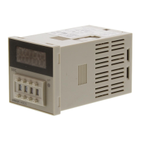
H3DR-A/P/M
H3DR-A/P/M
78
Operating mode Timing chart
G:
Signal
ON/OFF-delay
Basic operation
Power
Start
(see note)
Reset
(see note)
Output relay
(NC)
Power
indicator
t t t t
t-a t-a
Power
Output
t
t
t
t
Start
Output relay
(NO) (Output
indicator)
J:
One-shot output
Basic operation
Power
Start
(see note)
Reset
(see note)
Output relay
(NC)
Power
indicator
t
t-a
t-a
t
Is Is
t
1
!
0.6 s
Output
Start
Power
Output relay
(NO) (Output
indicator)
For power-on operation, short-circuit the start input and input common terminal.
The timer starts operating at the moment the power is turned on.
Note: 1. For NPN Input Models, “Start” stands for short-circuited C
1
and A
2
, and “Reset” stands for short-circuited D
1
and A
2
.
ForPNPInputModels,“Start”standsforvoltageapplicationbetweenB
1
andA
2
,and“Reset”stands forvoltageapplicationbetween
C
1
and A
2
.
2. The G and J modes are special modes. Order the H3DR-A
j
-300 special model for these modes.
Gate Signal Input
Power
Start
Gate
(see
note)
Reset
Output
relay
ON
OFF
ON
OFF
ON
OFF
ON
OFF
ON
OFF
t
1
t
2
Note: 1. This timing chart indicates the gate input in operating mode A (ON-delay operation).
2. The set time is the sum of t
1
and t
2
.
3. For NPN Input Models, “Gate” stands for short-circuited D
1
and A
2
.
For PNP Input Models, “Gate” stands for voltage application between D
1
and A
2
.

 Loading...