H3DR-A/P/M
H3DR-A/P/M
87
Input/Output
NPN Input Models
H3DR-A/-AS
Input contact
D
1
,C
1
,B
1
G, S, R
Input terminal
H3DR-A/-AS
**
A
2
*
A
1
L
Power supply
AC or DC
An appropriate input is applied to the input signal terminals of the
Timer when one of the input terminals (terminals B
1
,C
1
,orD
1
) and
thecommonterminal(terminalA
2
)fortheinputsignals areshort-cir-
cuited. Do not attempt to connect any input terminal to any terminal
other than the common terminal or to apply voltage across other
than the specified input and common terminals or the internal cir-
cuits of the Timer may be damaged.
* Power supply terminal A
2
is a common terminal for the input sig-
nals(G,S, R) to theTimer. Neveruseterminal A
1
as the common
terminal forthispurpose, otherwisethe internalcircuitoftheTim-
er may be damaged.
** Do not connect a relay or any other load between these two
points, otherwise the internal circuit of the Timer may be dam-
aged due to the high-tension voltage applied to the input termi-
nals.
H3DR-P
Input contact
C
1
S
Input terminal
H3DR-P
A
2
*
A
1
**
L
Power supply
AC or DC
An appropriate input is applied to the input signal terminals of the
Timer when the input terminal (terminal C
1
) and the common termi-
nal (terminal A
2
) for the input signal are short-circuited. Do not at-
tempt to connect any input terminal to any terminal other than the
common terminalortoapplyvoltageacross otherthanthespecified
inputandcommon terminals ortheinternal circuits of theTimermay
be damaged.
* Power supply terminal A
2
is a common terminal for the input sig-
nals (S) to the Timer. Never use terminal A
1
as the common ter-
minal for this purpose, otherwise the internal circuit of the Timer
may be damaged.
** Do not connect a relay or any other load between these two
points, otherwise the internal circuit of the Timer may be dam-
aged due to the high-tension voltage applied to the input termi-
nals.
PNP Input Models
H3DR-AP/-ASP
B
1
,C
1
,D
1
S, R, G
Input terminal
H3DR-AP/
H3DR-ASP
A
2
A
1
L
Power supply
AC or DC
Do not connect a relay or any other load between these two points,
otherwise the internal circuit of the Timer may be damaged due to
the high-tension voltage applied to the input terminals.
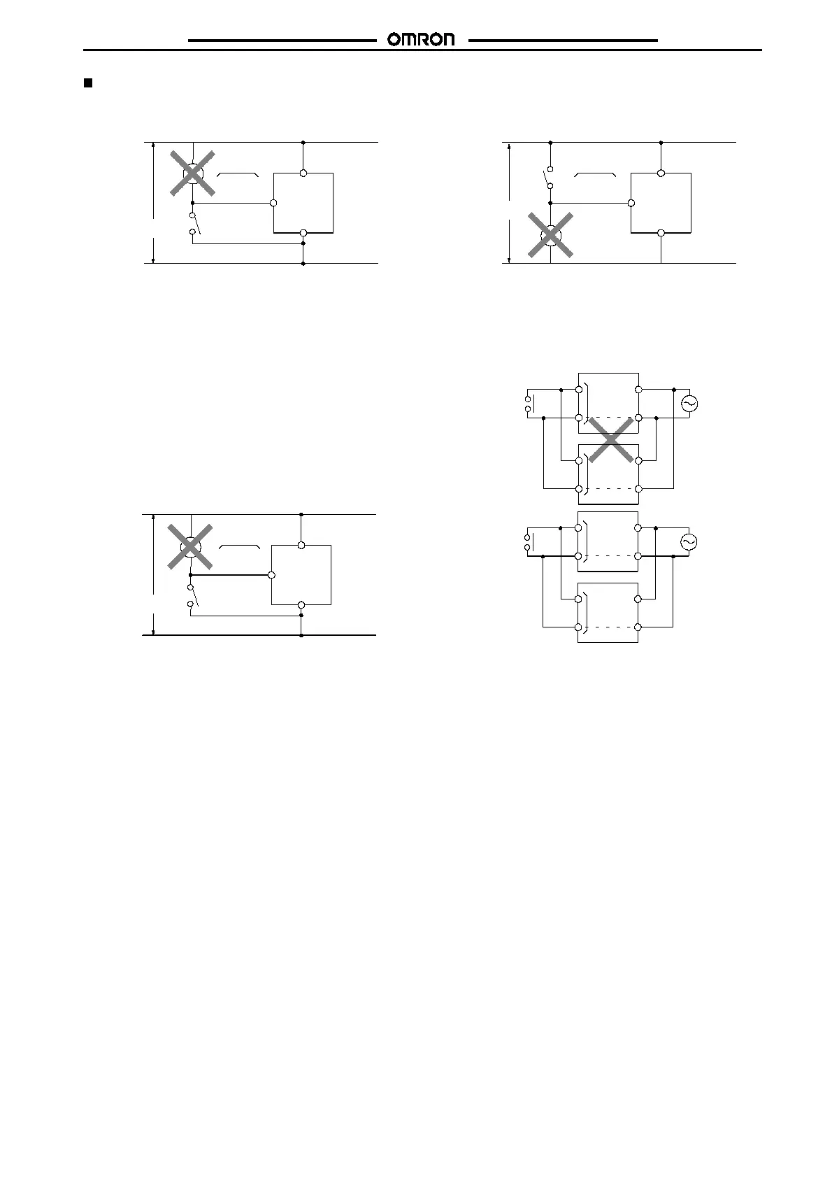
All Models
Incorrect
Contact or transistor for
external input signal
H3DR series timer
Input
terminal
Input
terminal
Power supply
Power supply
Correct
Short-circuit
current
Input
terminal
Input
terminal
When connecting a relay or a transistor as an external signal input
device, pay attention to the following points to prevent short-circuit-
ing due to a sneak current to the transformerless power supply.
If a relay or transistor is connected to two or more Timers, the input
terminals ofthoseTimersmustbewiredproperlysothattheywillnot
be different in phase or the terminals will be short-circuited to one
another (refer to the figures below).