24 Multifunction Digital Timer H5CX-A/-L (Timer Function)
Z Mode
Output quantity can be adjusted by changing the cycle time set in the adjustment level to 1 and by changing the ON duty (%) set value.
The set value shows the ON duty (%) and can be set to a value between 0 and 100 (%). When the cycle time is 0, the output will always be OFF.
When the cycle time is not 0 and when ON duty has been set to 0 (%), the output will always be OFF. When ON duty has been set to 100 (%), the
output will always be ON.
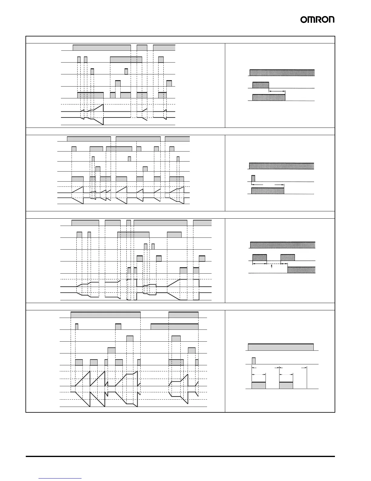
Output mode d: Signal OFF delay (Timer resets when power comes ON.)
Output mode E: Interval (Timer resets when power comes ON.)
Output mode F: Cumulative (Timer does not reset when power comes ON.)
Z mode: ON/OFF-duty adjustable flicker
0
UP
DOWN
0
Power
Start signal
Gate
Reset
Control output
Set value
Set value
Timing
diagram
**
Basic Operation
Power
Output
Timing
The control output is ON when the start signal is ON
(except when the power is OFF or the reset is ON).
The timer is reset when the time is up.
Start signal
input
*
Output functions only during start signal input when
setting is 0.
**
Start signal input is enabled during timing.
0
UP
DOWN
0
Power
Start signal
Gate
Reset
Control output
Set value
Set value
Timing
diagram
**
Basic Operation
Power
Output
Timing
Timing starts when the start signal comes ON.
The control output is reset when time is up.
While the start signal is ON, the timer starts when
power comes ON or when the reset input goes OFF.
Start signal
input
*
Output is disabled when the setting is 0.
**
Start signal input is enabled during timing.
0
UP
DOWN
0
Power
Start signal
Gate
Reset
Control output
Set value
Set value
Timing
diagram
*
Output is instantaneous when setting is 0.
Sustained
Basic Operation
Power
Output
Timing Timing
Start signal enables timing (timing is stopped when the
start signal is OFF or when the power is OFF).
A sustained control output is used.
Start signal
input
0
UP
DOWN
0
Power
Start signal
Gate
Reset
Control output
Cycle time
Cycle time
ON duty setting
(%) ON time
Timing
diagram
ON duty setting
(%) ON time
**
Basic Operation
Power
Output
Timing
ON duty (%)
Timing
(cycle time)
Timing
(cycle time)
Timing
ON duty (%)
Timing starts when the start signal goes ON.
The status of the control output is reversed
when time is up (ON at start).
While the start signal is ON, the timer starts when power
comes ON or when the reset input goes OFF.
Start signal
input
*
Normal output operation will not be possible if the set
time is too short.
Set the value to at least 100 ms (contact output type).
**
Start signal input is disabled during timing.