6
H7BX
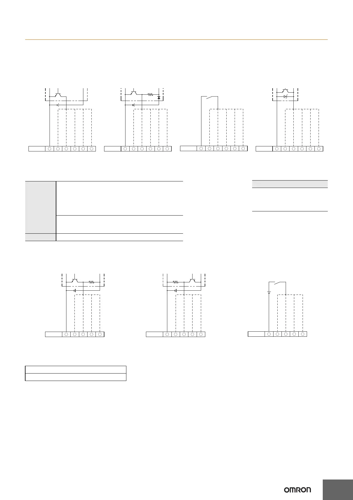
Input Connections
A no-voltage input (short-circuit or open) or voltage input can be selected for each input.
(The key protection input is always a no-voltage input (NPN input)).
No-voltage Inputs (NPN Inputs)
Note: When using the H7BX as a tachometer, do not use the CP2 input or total reset/reset 2 input.
No-voltage Input Signal Levels
Note: Use a DC power supply of 30 V max.
Voltage Inputs (PNP Inputs)
Note: When using the H7BX as a tachometer, do not use the CP2 input or total reset/reset 2 input.
Voltage Input Signal Levels
Note: 1. Use a DC power supply of 30 V max.
2. Input resistance: Approx. 4.7 kΩ
Open Collector Voltage Output Contact Input DC Two-wire Sensor
Terminal No.
Operates when the transistor turns ON.
0-V input
Reset/reset 1 input
CP2 input
CP1 input
Total reset/reset 2 input
Key protection input
PLC
or sensor
8 9
10 11 12 16
Sensor
Operates when the transistor turns ON.
8 9
10 11 12 16
Terminal No.
0-V input
Reset/reset 1 input
CP2 input
CP1 input
Total reset/reset 2 input
Key protection input
Operates when the contact turns ON.
8 9
10 11 12 16
Terminal No.
0-V input
Reset/reset 1 input
CP2 input
CP1 input
Total reset/reset 2 input
Key protection input
Operates when the transistor turns ON.
8 9
10 11 12 16
Terminal No.
0-V input
Reset/reset 1 input
CP2 input
CP1 input
Total reset/reset 2 input
Key protection input
No-contact
input
Short-circuit level
Transistor ON
• Residual voltage: 3 V max.
•
Impedance when ON: 1 kΩ max.
(The leakage current is approx. 12 mA when the impedance is
0
Ω
.)
Open level
Transistor OFF
• Impedance when OFF: 100 kΩ min.
Contact input
Use contact which can adequately switch 5 mA at 10 V.
Applicable Two-wire Sensors
• Leakage current: 1.5 mA max.
• Switching capacity: 5 mA min.
• Residual voltage: 3 VDC max.
• Operating voltage: 10 VDC
No-contact Input (NPN Transistor) No-contact Input (PNP Transistor) Contact Input
High level (Input ON): 4.5 to 30 VDC
Low level (Input OFF): 0 to 2 VDC
Sensor
Operates when the transistor turns OFF.
8 9
10 11 12
Terminal No.
0-V input
Reset/reset 1 input
CP2 input
CP1 input
Total reset/reset 2 input
Sensor
Operates when the transistor turns ON.
8 9
10 11 12
Terminal No.
0-V input
Reset/reset 1 input
CP2 input
CP1 input
Total reset/reset 2 input
Operates when the contact turns ON.
8 9
10 11 12
Terminal No.
0-V input
Reset/reset 1 input
CP2 input
CP1 input
Total reset/reset 2 input