36
H7CXH7CX
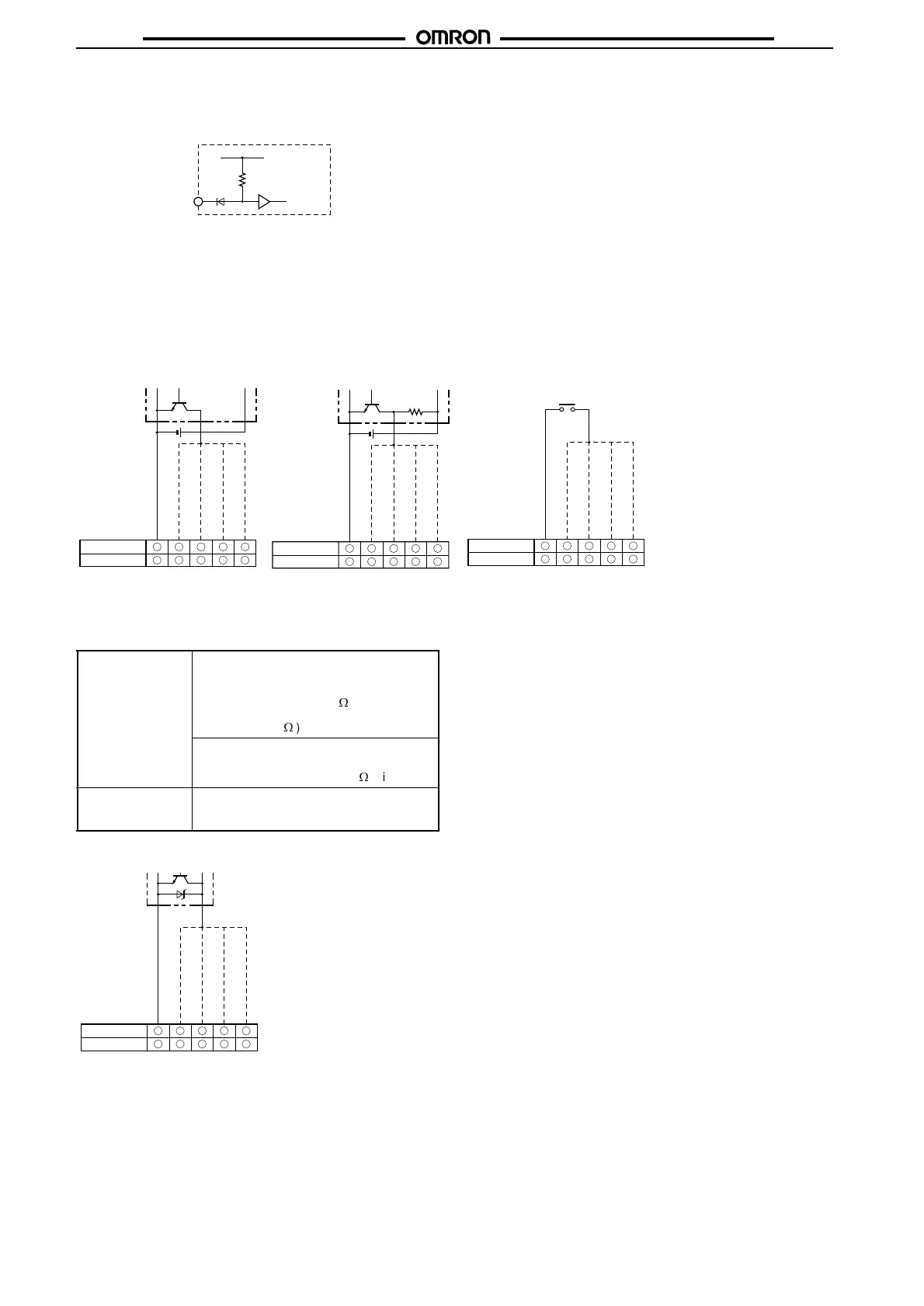
■ Input Circuits
CP1, CP2, Reset/Reset 1, and Total Reset/Reset 2 Input
Note: The circuit shown above is for no-voltage input (NPN input).
■
Input Connections
The inputs of the H7CX are no-voltage (short-circuit or open) inputs or voltage inputs.
No-voltage Inputs (NPN Inputs)
No-voltage Input Signal Levels
No-contact input Short-circuit level
Transistor ON
Residual voltage: 3 V max.
Impedance when ON: 1 K
W
max.
(The leakage current is 5 to 20 mA when the
impedance is 0
W
.)
Open level
Transistor OFF
Impedance when OFF: 100 K
W
min.
Contact input Use contact which can adequately switch
5 mA at 10 V.
Maximum applicable voltage: 30 VDC max.
6 7 8 9
3 7 5 6
10
4
6 7 8 9
3 7 5 6
10
4
PLC or
sensor
Open Collector
Voltage Output
Contact Input
Input
Reset/reset 1 input
CP2 input
CP1 input
H7CX-A@
H7CX-A11@
Operates when the transistor turns ON.
Sensor
Input
Reset/reset 1 input
CP2 input
CP1 input
H7CX-A@
Operates when the transistor turns ON.
H7CX-A11@
Input
Reset/reset 1 input
CP2 input
CP1 input
H7CX-A@
Operates when the contact turns ON.
H7CX-A11@
0V
0V
0V
Total reset/reset 2 input
Total reset/reset 2 input
Total reset/reset 2 input
Input
Reset/reset1 input
CP2 input
CP1 input
H7CX-A@
Operates when the transistor turns ON.
H7CX-A11@
Two-wire Sensor
0V
Total reset/reset 2 input

 Loading...


