6. EtherNet/IP Settings
10
6.2. Tag Data Link Allocation
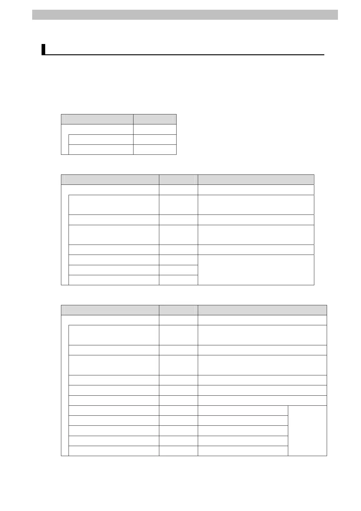
6.2.1. Data Types
The following data types are used for the data in the tag data links of the destination device.
■Definition of the data type to access the signals (Union)
This data type is used to access the control signals and status signals.
Data type name Data type
U_EIPFlag UNION
F BOOL[32]
W DWORD
■Definition of the data type to access the command area (Structure)
This data type is used to access the command area
Data type name Data type Destination device data
S_EIPOutput STRUCT -
CommonControlFlag
U_EIPFlag Sensor head common control signal
(32 bits)
SensorHead1ControlFlag U_EIPFlag Sensor head 1 control signal (32 bits)
SensorHead2ControlReserve
U_EIPFlag Sensor head 2 control signal (32 bits)
(reserved)
CommandCode DWORD Command code (CMD-CODE)
CommandParam1 UINT
CommandParam2 UINT
CommandParam3 DINT
Command parameter (CMD-PARAM)
■Definition of the data type to access the response/output areas (Structure)
This data type is used to access the response/output areas.
Data type name Data type Destination device data
S_EIPInput STRUCT -
CommonStatusFlag
U_EIPFlag Sensor head common status signal (32
bits)
SensorHead1StatusFlag U_EIPFlag Sensor head 1 status signal (32 bits)
SensorHead2StatusReserve
U_EIPFlag Sensor head 2 status signal (32 bits)
(reserved)
CommandCodeEcho DWORD Command code (CMD-CODE)
ResponseCode UDINT Response code (RES-CODE)
ResponseData UDINT Response data (RES-DATA)
MeasurementValueofTask1 DINT Measurement Value of Task1
MeasurementValueofTask2 DINT Measurement Value of Task2
MeasurementValueofTask3 DINT Measurement Value of Task3
MeasurementValueofTask4 DINT Measurement Value of Task4
MeasurementValueReserve DINT[4] Reserved
Output
data
0 to 7
(OutData
0 to 7)

 Loading...


