6. EtherNet/IP Settings
Additional Information
For details on the structure and union, refer to Tag Data Link Setting Methods in 6-3
Ethernet/IP Connection in Chapter 6 Communications with External Devices of the ZW
Series Displacement Sensor (Confocal Fiber Type) User's Manual (Cat. No. Z332).
Additional Information
With the Sysmac Studio, the data type is expressed as ARRAY[0..2] OF WORD when an
array is specified for a data type. However, the data type of an array is simplified in this
document (e.g. WORD[3]).
It is possible to set either of the following to specify an array for a data type with the Sysmac
Studio.
•ARRAY[0..2] OF WORD
•WORD [3]
In the example above, 3 WORD array elements are secured.
6.2.2. Data Allocation
The data in the tag data links of the destination device are allocated to the global variables of
the Controller. The relationship between the device data and the global variables is shown
below.
The following global variables are set in the "Configuration file".
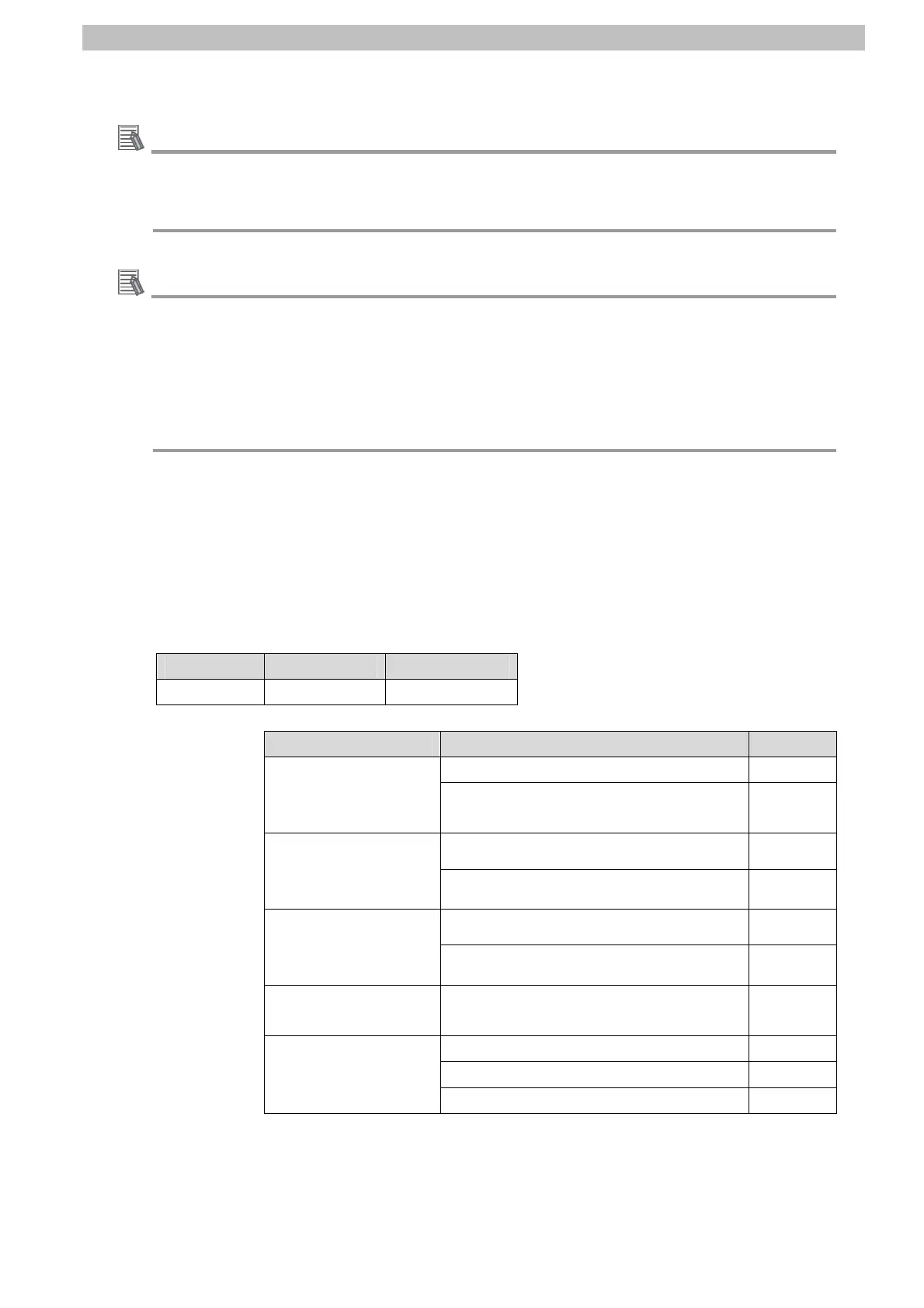
■Output area (Controller → Displacement Sensor)
Variable Data type Data size
EIPOutput S_EIPOutput 24 bytes
Offset (word) Destination device data Name Data type
EIPOutput.CommonControlFlag.F
*4
BOOL[32]
+0 and +1
Control output 1
*1
(32 bits)
(Data type: U_EIPFlag)
EIPOutput.CommonControlFlag.W
*4
DWORD
EIPOutput.SensorHead1ControlFlag.F
*5
BOOL[32]
+2 and +3
Control output 2
*2
(32 bits)
(Data type: U_EIPFlag)
EIPOutput.SensorHead1ControlFlag.W
*5
DWORD
EIPOutput.SensorHead2ControlReserve.F
*6
BOOL[32]
+4 and +5
Control output 3
*3
(32 bits)
(Data type: U_EIPFlag)
EIPOutput.SensorHead2ControlReserve.W
*6
DWORD
+6 and +7
Command code
(CMD-CODE)
EIPOutput.CommandCode DWORD
+8 EIPOutput.CommandParam1 UINT
+9 EIPOutput.CommandParam2 UINT
+10 and +11
Command parameter
(CMD-PARAM)
EIPOutput.CommandParam3 DINT
*1: Sensor head common control signal
*2: Sensor head 1 control signal
*3: Sensor head 2 control signal (reserved)
*4: Details on allocation of sensor head common control signal
11

 Loading...


