6. EtherNet/IP Settings
15
RESETSTAT1: Reset execution state bit: Turns ON when the displacement
sensor is in the reset execution state.
LIGHT1: Logical beam lighting state bit: Turns ON when the logical beam is
lit.
STABILITY1: Measurement position bit: Turns ON when the measured
value is in the measuring range.
ENABLE1: Measurement state bit: Turns ON when the displacement sensor
is ready for measurement.
GATE1: Data output completed bit: Turns ON when the displacement sensor
completes control data output when hold is set.
OR1: Overall judgment result bit: Turns ON when even one of the judgment
result of the displacement sensor TASK1 to 4 is other than PASS.
ZEROSTAT1_T1 to 4: Zero reset bit: Turns ON when the displacement
sensor TASK1 to 4 is in the zero reset execution state.
HIGH1_T1 to 4: HIGH output bit: Turns ON when the judgment result of the
displacement sensor TASK1 to 4 is HIGH (HIGH threshold <
measured value).
PASS1_T1 to 4: PASS output bit: Turns ON when the judgment result of the
displacement sensor TASK1 to 4 is PASS (LOW threshold ≤
measured value ≤ HIGH threshold).
LOW1_T1 to 4: LOW output bit: Turns ON when the judgment result of the
displacement sensor TASK1 to 4 is LOW (LOW threshold >
measured value).
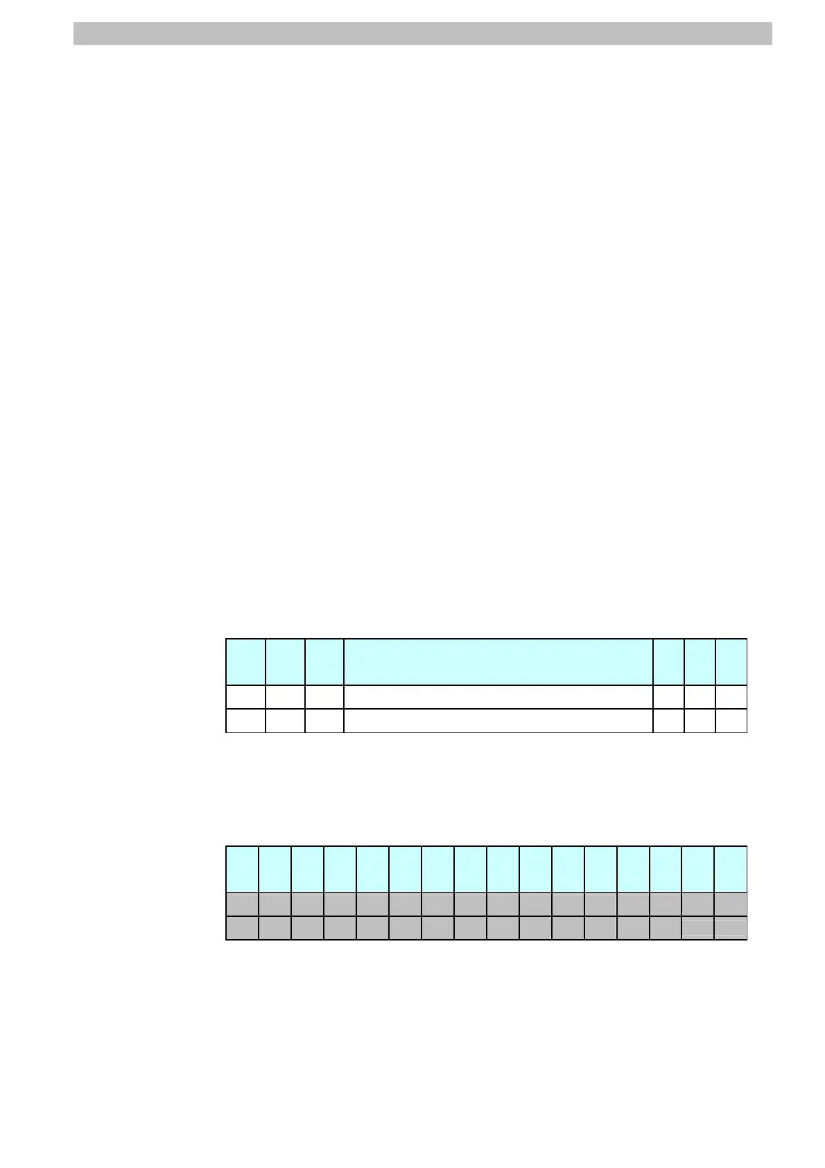
Allocation of EIPOutput.SensorHead1StatusFlag.W variable
Offset
(word)
15 14 13 … 2 1 0
+2 15 14 13 … 2 1 0
+3 31 30 29 … 18 17 16
Bits 31 to 0: EIPOutput.SensorHead1StatusFlag.W uses DWORD data from
offset + 2 words.
*6: Details on allocation of sensor head 2 control signal (reserved)
Allocation of EIPOutput.SensorHead2StatusReserve.F variable
Offset
(word)
15 14 13 12 11 10 9 8 7 6 5 4 3 2 1 0
+4
+5

 Loading...


