6. EtherNet/IP Settings
14
+20 and +21 Output data 4 (DATA4)
+22 and +23 Output data 5 (DATA5)
+24 and +25 Output data 6 (DATA6)
+26 and +27 Output data 7 (DATA7)
EIPInput.MeasurementValueReserve DINT[4]
*1: Sensor head common status signal
*2: Sensor head 1 status signal
*3: Sensor head 2 status signal (reserved)
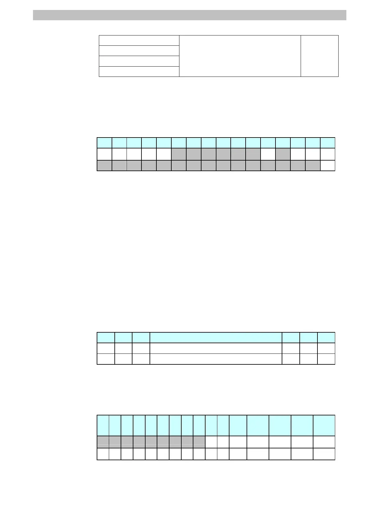
*4: Details on allocation of sensor head common status signal
Allocation of EIPInput.CommonStatusFlag.F variable
Offset (word) 15 14 13 12 11 10 9 8 7 6 5 4 3 2 1 0
+0
BANK1
_E
BANK1
_D
BANK1
_C
BANK1
_B
BANK1
_A
RUN READY
SYNC
FLG
FLG
+1
ERR
FLG: Control command completion bit: Turns ON when the displacement
sensor completes control command execution.
SYNCFLG: Measurement synchronization completion bit: Turns ON when
the displacement sensor executes measurement synchronization
processing and the state changes to one where normal measured
values can be output.
READY: Ready bit: Turns ON when the displacement sensor can execute
control commands or measurement synchronization processing.
RUN: Run screen bit: Turns ON when the displacement sensor is in the
RUN mode.
BANK1_A to E (BANKOUT1_A to E): Current bank number bit: Outputs the
currently specified bank number. It expresses the bank number in
combinations of BANKOUTx_A to E.
ERR: Error bit: Turns ON when a displacement sensor error is detected.
Allocation of EIPInput.CommonStatusFlag.W variable
Offset (word) 15 14 13 … 2 1 0
+0
15 14 13 … 2 1 0
+1
31 30 29 … 18 17 16
Bits 31 to 0: EIPInput.CommonStatusFlag.W uses DWORD data from offset
+ 0 word.
*5: Details on allocation of sensor head 1 status signal
Allocation of EIPOutput.SensorHead1StatusFlag.F variable
Offset
(word)
15 14 13 12 11 10 9 8 7 6 5 4 3 2 1 0
+2
OR1
GATE
1
ENABLE
1
STABLITY1
LIGHT1
RESETSTA
T1
HOLDSTAT
1
+3
LOW
1_T4
PASS
1_T4
HIGH
1_T4
LOW
1_T3
PASS
1_T3
HIGH
1_T3
LOW
1_T2
PASS
1_T2
HIGH
1_T2
LOW
1_T1
PASS
1_T1
HIGH1_
T1
ZEROSTAT
_T4
ZEROSTAT
_T3
ZEROSTAT
_T2
ZEROSTAT
_T1
HOLDSTAT1: Hold execution status bit: Turns ON when the displacement
sensor is in the hold sampling period.

 Loading...


