9. Appendix 1 Detailed Settings of the Tag Data Links
HIGH1_T1 t
o 4: HIGH output bit: Turns ON when the judgment result of the
displacement sensor TASK1 to 4 is HIGH (HIGH threshold <
measured value).
PASS1_T1 to 4: PASS output bit: Turns ON when the judgment result of the
displacement sensor TASK1 to 4 is PASS (LOW threshold ≤
measured value ≤ HIGH threshold).
LOW1_T1 to 4: LOW output bit: Turns ON when the judgment result of the
displacement sensor TASK1 to 4 is LOW (LOW threshold >
measured value).
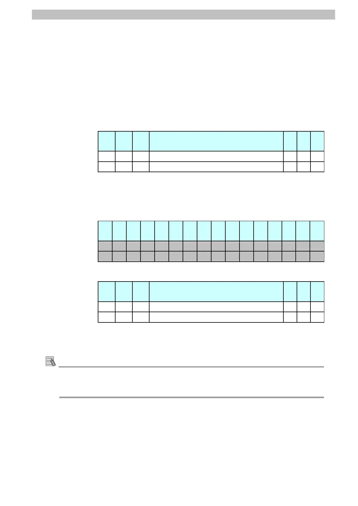
Allocation of EIPOutput.SensorHead1StatusFlag.W variable
Offset
(word)
15 14 13 … 2 1 0
+2 15 14 13 … 2 1 0
+3 31 30 29 … 18 17 16
Bits 31 to 0: EIPOutput.SensorHead1StatusFlag.W uses DWORD data from
offset + 2 words.
*6: Details on allocation of sensor head 2 control signal (reserved)
Allocation of EIPOutput.SensorHead2StatusReserve.F variable
Offset
(word)
15 14 13 12 11 10 9 8 7 6 5 4 3 2 1 0
+4
+5
Allocation of EIPOutput.SensorHead2StatusReserve.W variable
Offset
(word)
15 14 13 … 2 1 0
+4 15 14 13 … 2 1 0
+5 31 30 29 … 18 17 16
Bits 31 to 0: EIPOutput.SensorHead2StatusReserve.W uses DWORD data
from offset + 2 words.
Additional Information
For details on the structure and union, refer to 6-3 Ethernet/IP Connection in Chapter 6
Communications with External Devices of the ZW Series Displacement Sensor (Confocal
Fiber Type) User's Manual (Cat. No. Z332).
50

 Loading...


