4-15
4 Installation and Wiring
NJ-series CPU Unit Hardware User’s Manual (W500)
4-3 Mounting Units
4
4-3-2 Connecting Controller Components
3 Attach the End Cover to the Unit on the far right side of the Rack.
There is no Backplane for the NJ-series. The Controller is constructed by connecting Units
together using the connectors on the sides.
Precautions for Correct UsePrecautions for Correct Use
• Always turn OFF the power supply before connecting Units to each other.
• Always turn OFF the power supply to the entire system before replacing a Unit.
• A maximum of 10 Units can be connected in any one CPU Rack or Expansion Rack. If you
connect more than that number, an Incorrect Unit/Expansion Rack Connection error (a major
fault level Controller error) will occur, and the NJ-series CPU Unit will not operate.
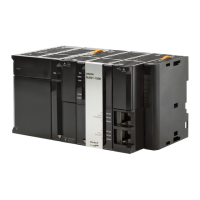
CPU Rack
Power Supply
Unit
CPU Unit
(I/O Control Unit) *1
Configuration Units (10 max.)
End Cover
(included with
CPU Unit)
*1: Connect the I/O Control Unit directly to the CPU Unit to enable connecting Expansion
Racks.
*2: Connect the I/O Interface Unit directly to the Power Supply Unit.
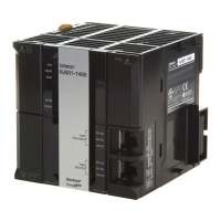
Expansion Rack
I/O Interface Unit *2
End Cover
(included with
I/O Interface Unit)
Power Supply
Unit
Configuration Units (10 max.)
 Loading...