1-2 Part Names and Functions
1
1
16 NP Introduction Manual
NP Overview
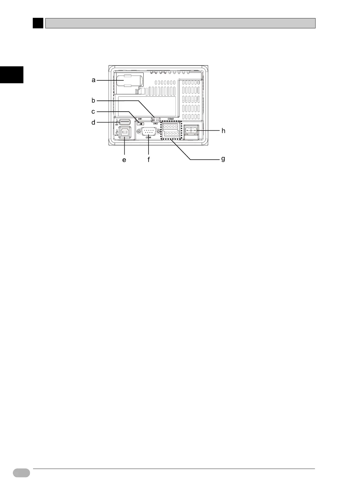
●Rear View
a Battery cover
Open this cover to get access to the battery slot.
b DIP Switches (SW2)
DIP switches for switching between RS-422A and RS-485, and for setting the
terminating resistance when connecting COM2 (RS-422A/485) to the host.
c Slide Switch (SW1)
Slide switch is used for booting the system menu. To display the system menu,
slide this switch to the ON position (left) and turn on the NP. This switch is
usually kept in the OFF position (right).
For details on the system menu, refer to NP Series User’s Manual (V096).
d USB Connector type A (host)
This connector is used for connecting with a USB flash memory to transfer
screen data and system programs created with NP-Designer.
e USB Connector type B (slave)
This connector is used for connecting with a PC via USB cable to transfer
screen data and system programs created with NP-Designer.
f Serial Port Connector (COM1)
9-pin connector for RS-232C connection for connecting with the host.
g Serial Port Connector (COM2)
10-pin terminal blocks for RS-422A/485 connections for connecting with the
host.
h Power input connector
This connector is used for connecting with 24VDC power.
Note Check system safety before you turn the power ON/OFF.
 Loading...


