3-8 Installing the Controller Link Interface Unit
● Switch Settings
The following settings are made at the factory. Do not change these settings.
Item Switch Setting
Memory address Memory allocation switch SW1: ON
SW2: ON
SW3: OFF
SW4: ON
Interrupt level Interrupt shorting pin Set to IRQ10.
● Setting Terminating Resistance
Turn the built-in terminating resistance ON or OFF using the terminating resistance switch
(slide switch). Terminating resistance is required at the both ends of a wired network to ab-
sorb unnecessary signals and reduce the noise. The Controller Link Support Board has built-
in terminating resistance, which can be connected simply by setting the slide switch to ON.
Set the switch to ON to connect the terminating resistance at both end nodes in wired net-
works and set the switch to OFF at all other nodes.
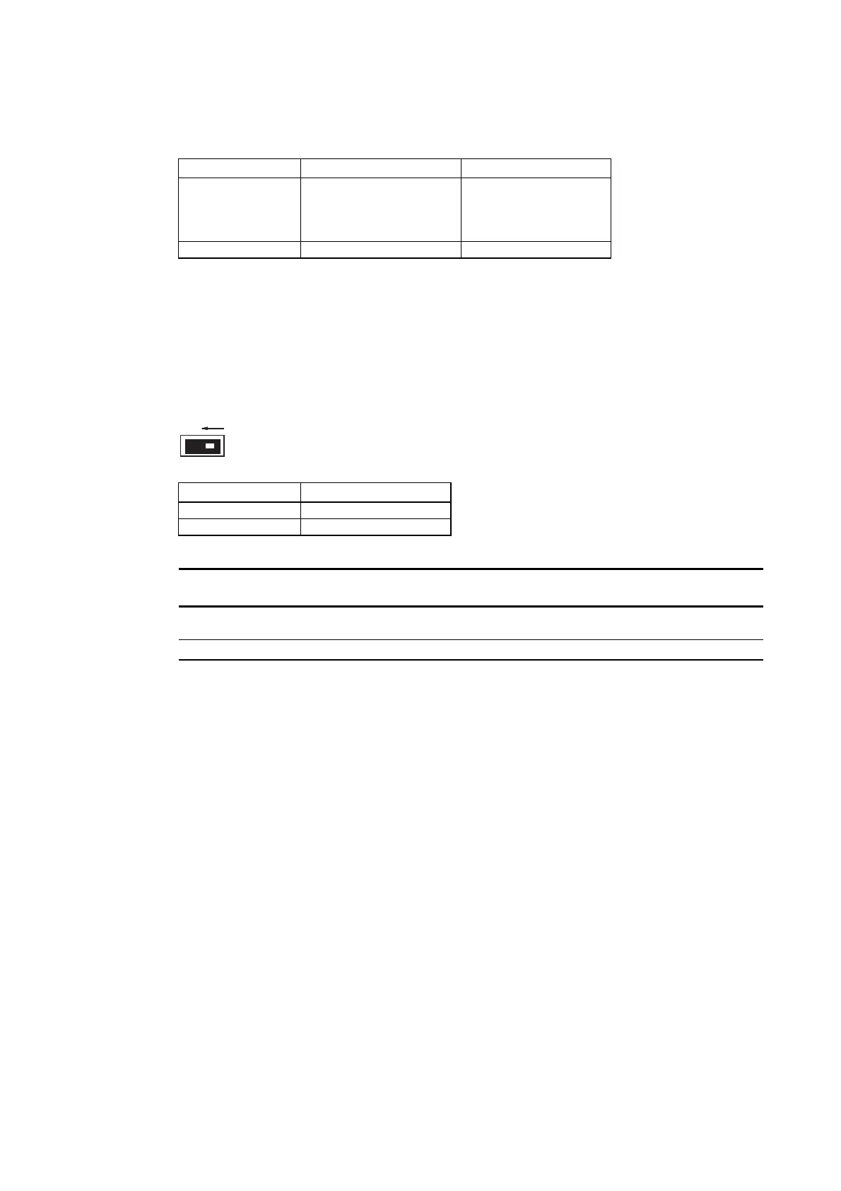
ON
Setting Terminating resistance
OFF (factory setting) Not connected
ON Connected
Note This switch can be set after the Controller Link Interface Unit is installed on the PT.
Turn OFF the power of the PT before changing the setting.
Reference This switch is set to OFF by default (terminating resistance disconnected).
3-42

 Loading...


