5-1 Connecting to Host Via Ethernet
Unit number 04
Unit number 02
Network 2
Network 3
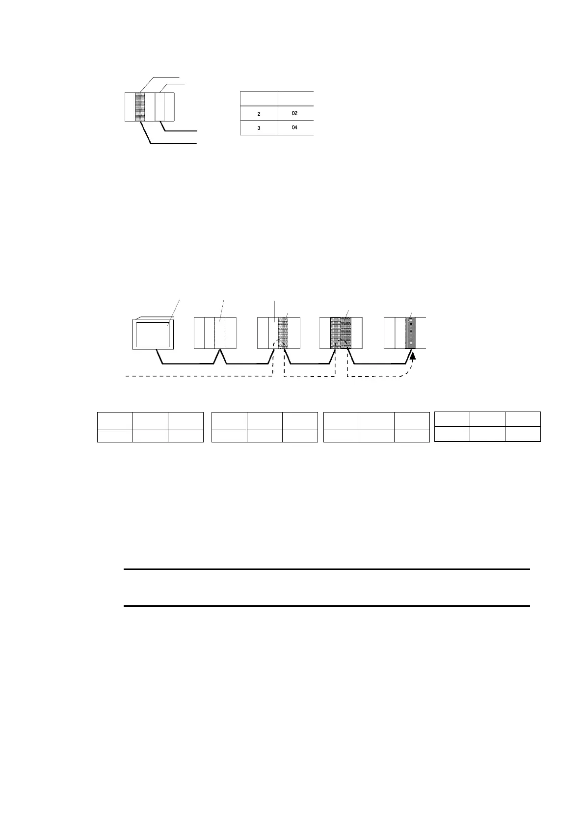
Local network table
Local network
address
Unit number
Remote Network Table
The remote network table provides the node and network address corresponding to the initial
relay point (first point the data must pass) en route to a target network (end network) not di-
rectly connected to the local PLC. The table specifies the route from the relay point to the end
network.
PT at local
node
Node 1 Node 2
Node 3
Relay PLC
(a)
Node 2
Relay PLC
(b)
Node 1
Desti-
nation
Node 2
Network 1 Network 2 Network 3
Node 1
Relay Network Table for Local PT
Destination
network
address
3 1 3
Relay
network
address
Gateway
node
address
Meaning: To go to network 3,
first go to node 3 of network 1.
Relay Network Table for PLC (a)
3 2 2
Destination
network
address
Gateway
node
address
Relay
network
address
Meaning: To go to network 3,
first go to node 2 of network 2.
Relay Network Table for PLC (b)
1 2 1
Meaning: To go to network 1,
first go to node 1 of network 2.
Relay Network Table for Destination
Destination
network
address
Relay
network
address
Gateway
node
address
1 3 1
Meaning: To go to network 1,
first go to node 1 of network 3.
Destination
network
address
Gateway
node
address
Relay
network
address
Routing tables are created using the CX-Programmer and then transferred to the host. Refer
to the CX-Programmer User Manual for actual procedures.
The methods for setting each Unit are described next.
• CS-series PLCs
Note
• Always turn OFF the power to the PLC before setting the rotary switches.
• Create I/O tables for the CPU Unit when setting the unit number for the first time or chang-
ing settings.
CS1G/CS1H and CS1G/CS1H-H Ethernet Units:
CS1W-ETN01
CS1W-ETN11
CS1W-ETN21
5-8
 Loading...


