3-2SectionConnecting Link Adapters
20
Communications Specifications (RS-422A/485 Interface)
Item Specification
Baud rate 115.2k bps max. (depends on the RS-232C baud
rate)
Transmission distance 500 m max.
Terminal block configuration 8-terminal detachable terminal block, M3.0
Insulation Non-insulated (See note.)
Note The
RS-422A/RS-485 connector is not insulated from the RS-232C
connector
.
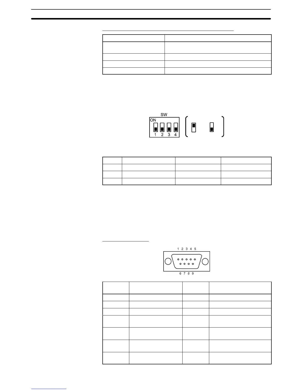
The NS-AL002 Link Adapter has a 4-pin DIP switch that sets the RS-422A/
RS-485 communication conditions. Set the DIP switch before connecting the
communications cable.
ON OFF
The
following table shows the functions of the DIP
switch pins. The factory de
-
faults are OFF for all 4 pins.
Pin(s) Function ON OFF
1 Communications
mode
RS/CS control No RS/CS control
2 and 3
Communications method 2-wire (RS-485) 4-wire (RS-232C)
4 Terminating resistance Terminator ON Terminator OFF
When
using 1:1 NT Link communications, set the communications
mode to “No
RS/CS control” by turning OFF pin 1.
When using 1:N NT Link communications (standard or high-speed), set the
communications mode to “RS/CS control” by turning ON pin 1.
The Link Adapter has an RS-232C connector and a terminal block for an
RS-422A/485
interface connection.
The pin arrangements for the RS-232C con
-
nector and the RS-422A/485 terminal block are as follows.
RS-232C Connector
Pin Signal name Code
Signal direction
(Link Adapter ⇔ NT21)
1 Not used --- ---
2 Receive data RD Link Adapter ← NT21
3 Send data SD Link Adapter → NT21
4 Clear to send
(shorted to RS internally)
CS Link Adapter ← NT21
5 Request to send
(shorted to CS internally)
RS Link Adapter → NT21
6 +5 V (30 mA) input for
Link Adapter
+5 V Link Adapter ← NT21
7 and 8
Not used --- Pins 7 and 8 are shorted
internally
DIP Switch Settings
Pin Allocation

 Loading...


