3-2SectionConnecting Link Adapters
21
Pin
Signal direction
(Link Adapter ⇔ NT21)
CodeSignal name
9 Signal ground SG ---
Connector
hood
Function ground FG ---
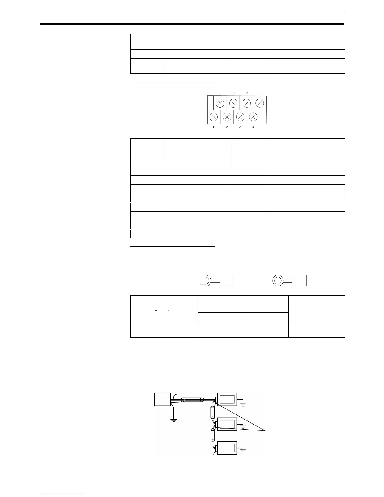
RS-422A/485 Terminal Block
Pin Signal name Code
Signal direction
(Link Adapter ⇔
RS-422A/485 device)
1 Frame ground FG Connects to the Unit’s
functional ground terminal.
2 Receive data (+) RDB (+) Link Adapter ← Device
3 Send data (+) SDB (+) Link Adapter → Device
4 Request to send (+) RSB (+) Link Adapter → Device
5 No contact NC ---
6 Receive data (–) RDA (–) Link Adapter ← Device
7 Send data (–) SDA (–) Link Adapter → Device
8 Request to send (–) RSA (–) Link Adapter → Device
Compatible Crimp Terminals
Use crimp terminals for M3 screws.
Fork
terminal
6.2 mm max.
Round terminal
6.2 mm max.
Maker Style Model Compatible wire
J.S.T. Mfg Co., Ltd.
Fork V1.25-N3A
AWG22 to AWG16
Round RAV1.25-3
(0.3 to 1.65 mm
2
)
When using RS-422A or RS-485 cables for long-distance
communications,
do
not
ground the shield at both ends of the communications line because large cur
-
rents can flow through the shield due to the difference in potential at the two
grounding
points. W
e recommend grounding the shield at one end, as shown in
the following diagram.
Signal
line
Host
RS-422A/485
shield
PT
PT
PT
NS-AL002
Connect to FG on the
terminal block.
RS-422A/485 Cable
Shield Connections

 Loading...


