3-2SectionConnecting Link Adapters
23
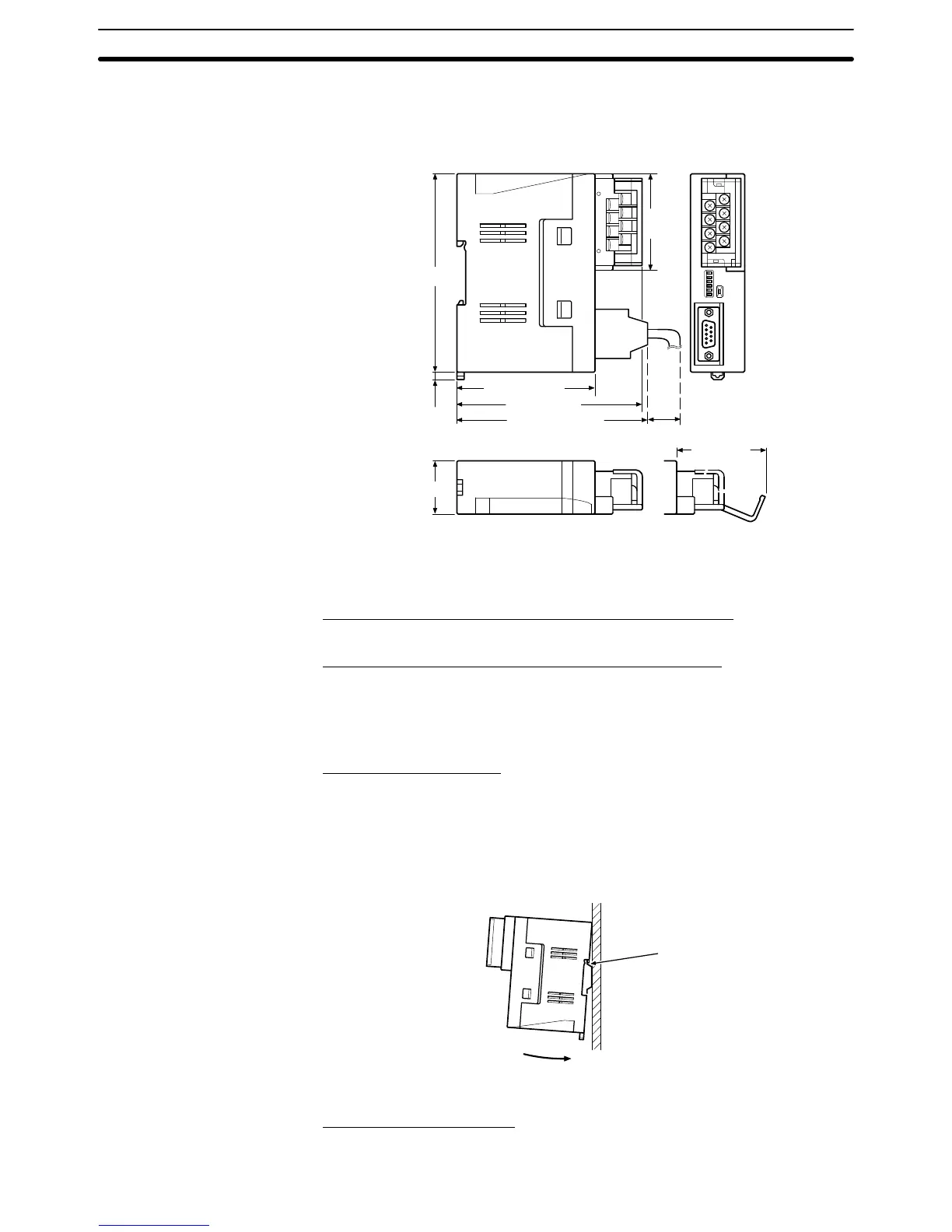
The
following diagram shows the dimensions of the NT
-AL001
Link Adapter
. All
dimensions are in mm.
om on
R
NT–AL001-E
100.2
(3.94)
74.5 (2.93)
1
10 (4.33)
4 (0.16)
30 (1.18)
45 (1.77)
53.5
(2.11)
(30)
(1.18)
105 (4.13) max.
Units: mm (inch)
Dimensions with RS-422A Terminal Block Cover Closed
30 114 100.2 mm (W H D)
Dimensions with RS-422A Terminal Block Cover Open
30 114 119.5 mm (W H D)
The
NT
-AL001 Link Adapter can be mounted on a DIN T
rack or in a control pan
-
el. The Link Adapter’s RS-422A terminal block can be removed easily.
Mounting to a DIN Track
Latch
the hook (a) on the rear of the Link Adapter onto the top edge of the DIN
Track,
and pivot the Link Adapter downwards (b) as shown in the diagram below
.
Next,
fit End Plates at the right and left of the Link Adapter to secure it so that it
cannot shift laterally.
(b)
(a)
Removal from a DIN Track
Remove the End Plates from the right and left of the Link Adapter
, insert a flat
Dimensions
Installation and Removal

 Loading...


