3-2SectionConnecting Link Adapters
24
blade screwdriver into the catch at the bottom of the Link Adapter, and pull it
down to release the catch.
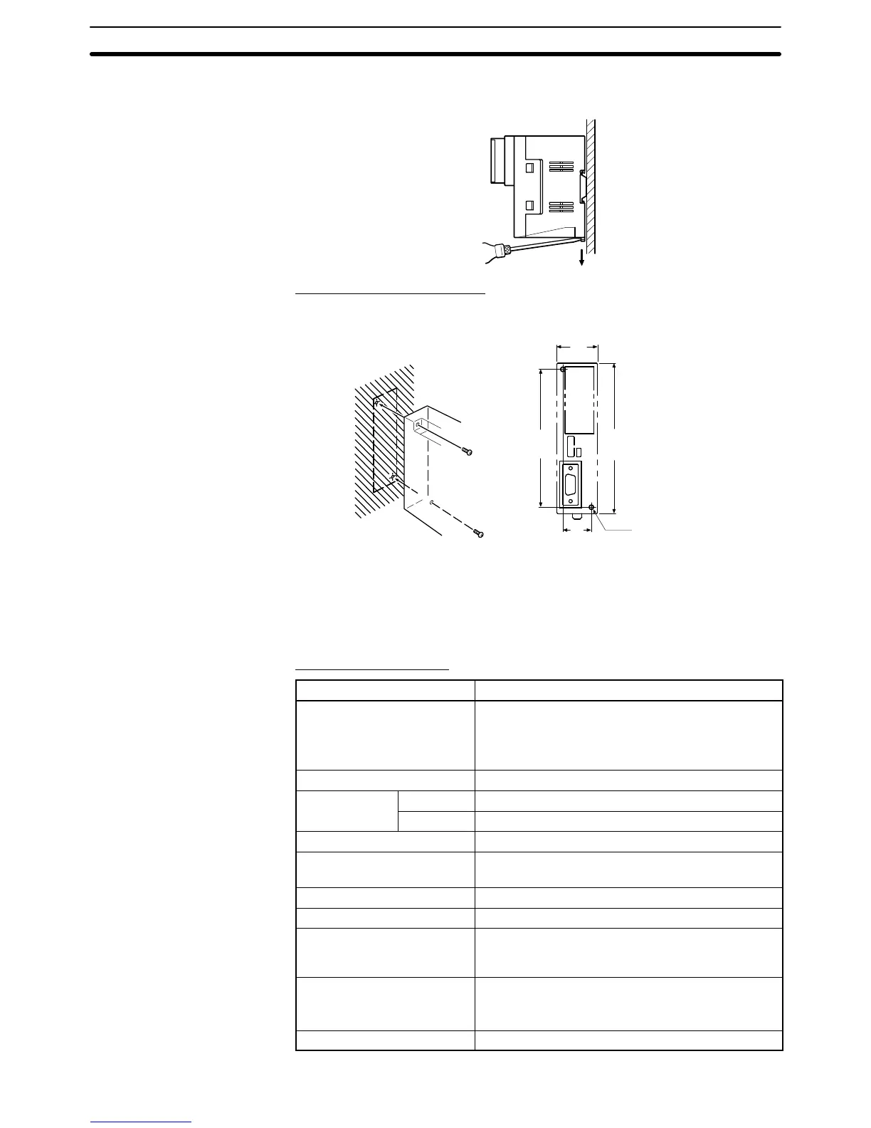
Mounting to a Control Panel
The control panel must be at least 2 mm (5/64 inch) thick. Drill two mounting
screw holes in a control panel and secure the Link Adapter with screws.
(1.18)
30
21
100
(3.94)
110
(4.33)
2-M4
holes
Units: mm (inch)
(0.83)
Note The
control
panel must be at least 2 mm (5/64 inch) thick for a secure and strong
mount.
The
following tables list the NT
-AL001 Link Adapter
’
s general and communica
-
tions specifications.
General Specifications
Item Specification
Dimensions With RS-422A terminal block cover closed:
30 114 100.2 mm (W H D)
With RS-422A terminal block cover open:
30 114 119.5 mm (W H D)
Weight 200 g max.
Ambient Operating
0 to 55
_C
temperature
Storage
–20 to 75
_C
Operating ambient humidity 10% to 90% (with no condensation)
Rated power supply voltage +5 V " 10%
(through pin 6 of the RS-232C connector)
Rated power supply current 150 mA max.
Inrush current 0.8 A max.
Insulation resistance
20 M
Ω min., measured between the RS-422A
terminal signal lines and FG terminal (with a
500 VDC megger)
Dielectric strength 1,500 VAC for 1 minute between the RS-422A
terminal signal lines and the FG terminal
Leakage current: 10 mA max.
Operating environment No corrosive gases
Specifications

 Loading...


