4-1SectionConnecting to the RS-232C Port at the Host
58
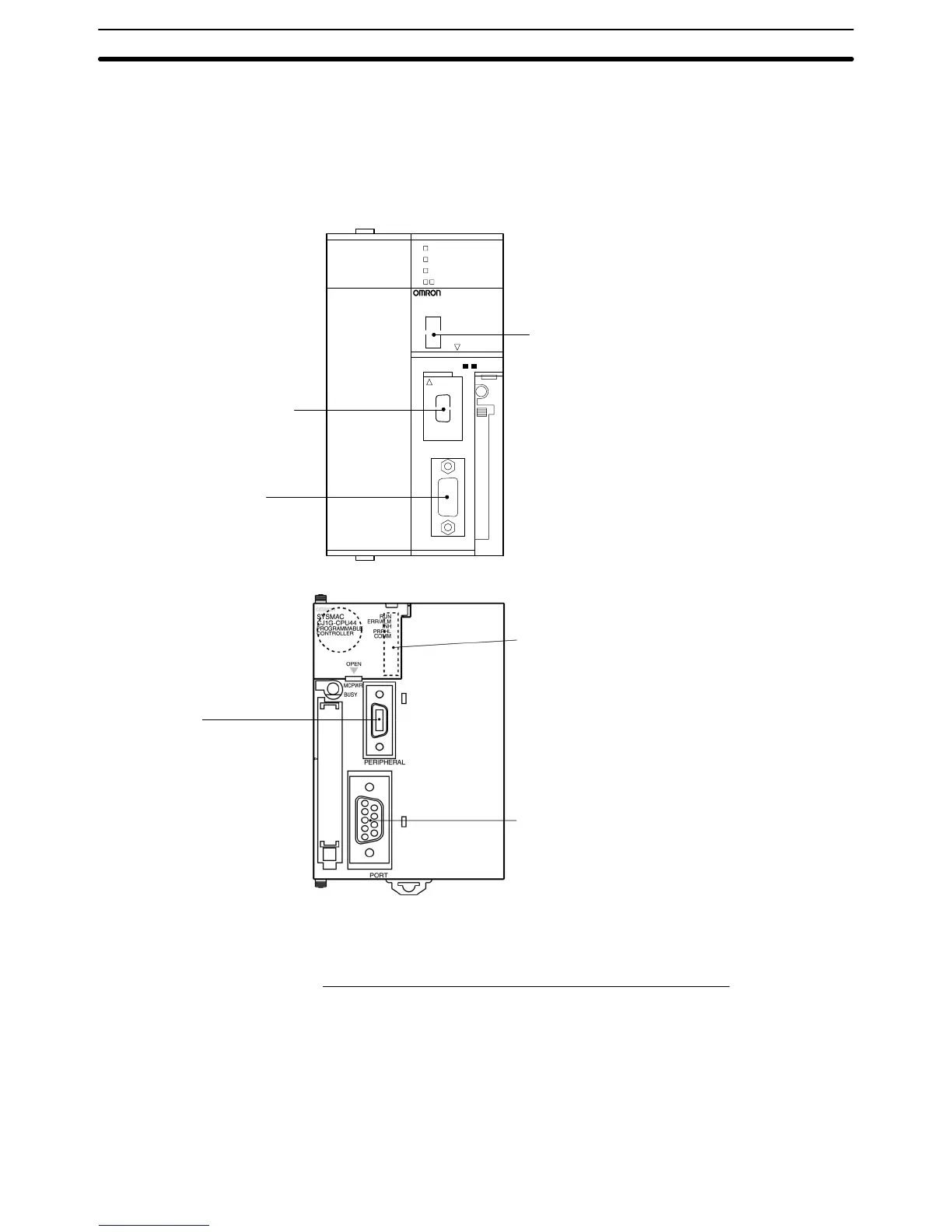
Setting the Front Switches
Set
pins 4 and 5 of the CPU Unit DIP switch in accordance with the port that the
NT21 is connected to.
Peripheral
port
This is used mainly for
connection to the
Programming Device.
(This also supports the
RS-232C Unit connection.)
RS-232C port
This is used mainly for
connection to the
RS-232C Unit.
(This also supports a
CX-Programmer
connection.)
DIP switches (inside the battery storage)
• Set pin 4 to ON (establishing communication in ac-
cordance
with PC Setup) when connecting the NT21
to
the peripheral port.
• Set
pin 5 to OFF (establishing communication in ac
-
cordance
with PC Setup) when connecting the NT21
to
the RS-232C port.
SYSMAC
CS1G
PROGRAMMABLE CONTROLLER
CPU4
2
OPEN
OPEN
PERIPHERAL
PORT
BUSY
RUN
ERR/ALM
INH
PRPHL/COMM
MCPWR
CS1G/H, CS1G/H-H
CJ1G
DIP switches (inside the battery storage)
• Set pin 4 to ON (establishing communication in ac-
cordance
with PC Setup) when connecting the NT21
to
the peripheral port.
• Set
pin 5 to OFF (establishing communication in ac
-
cordance
with PC Setup) when connecting the NT21
to
the RS-232C port.
Peripheral port
This is used mainly for
connection to the Programming
Device.
(This also supports the
RS-232C Unit connection.)
RS-232C port
This is used mainly for connection to the RS-232C
Unit.
(This also supports a CX-Programmer connection.)
Connecting to CS-series Serial Communications Board
Serial
Communications Board equipped with a RS-232C port for CS-series CPU
Units:
CS1W
-SCB41/21
CPU Unit Allocation DM Area Settings
Setting
is written from the Programming Device
(a Programming Console or CX-
Programmer) directly into the allocated DM Area (PC Setup) of the CPU Unit.
After
the setting is written, it becomes ef
fective by turning the
power ON, restart
-
ing the Unit, restarting the communication port, or execution of the STUP
instruction.

 Loading...


